 en
en
 русский
 Deutsch
Wind Turbine Generator Base & Generator Frame: Engineering Guide
Every megawatt a wind turbine delivers passes through one critical junction: the interface between the generator and the rest of the drivetrain. At that junction sits the generator base — a fabricated steel structure that most turbine specifications list as a supporting component but which, in engineering reality, governs generator alignment, load transfer, and long-term drivetrain reliability. For engineers specifying nacelle components and procurement teams sourcing welded box-type generator frames and housings for wind turbines, understanding what this component actually does — and what happens when it is under-engineered — is essential to making sound decisions.
Content
- 1 The Generator Base: Where Structural and Mechanical Demands Converge
- 2 Three Load Paths Every Generator Frame Must Handle
- 3 Cast Steel vs Welded Steel: Choosing the Right Construction Method
- 4 Alignment Precision: Why a Few Millimeters Define Generator Lifespan
- 5 Direct-Drive vs Geared Turbines: Different Frames for Different Demands
- 6 Manufacturing and Quality Standards for Wind Turbine Generator Frames
The Generator Base: Where Structural and Mechanical Demands Converge
Inside the nacelle, the structural layout divides into two zones. The front section — built around the main frame or bedplate — carries the yaw system, main shaft bearing, and gearbox. Immediately behind it, connected to the main frame at the front and supporting the full static weight of the generator at the rear, is the generator base, also referred to in engineering documentation as the generator frame, rear frame, or generator support structure.
This position is not incidental. The generator base bridges the mechanical drivetrain and the structural enclosure of the nacelle. It must simultaneously satisfy three demands that rarely coexist comfortably: it must be rigid enough to maintain dimensional stability under multi-directional dynamic loading; it must be precise enough at its mounting surfaces to hold generator-to-gearbox alignment within a tolerance measured in fractions of a millimeter; and it must be light enough and compact enough to fit within nacelle geometry that is already tightly constrained by the main frame, cover, and auxiliary systems.
In geared turbines, the generator base connects the generator to the high-speed output shaft of the gearbox. In direct-drive turbines — where the rotor connects to the generator without intermediate gearing — it supports the generator on the main shaft directly, carrying substantially higher torque and radial loads with no gearbox to distribute them. The same component name, two very different structural briefs.
Three Load Paths Every Generator Frame Must Handle
Specifying a generator frame without a clear picture of its load environment leads to either over-engineering that adds unnecessary weight and cost, or under-engineering that produces fatigue failures in service. Three distinct load paths run through the frame simultaneously during operation.
Static gravitational loading is the most straightforward. The generator in a utility-scale wind turbine typically weighs between 15 and 80 metric tons depending on power class and drivetrain type. This weight is transferred through the generator mounting feet, through the frame structure, and into the main frame connection points at the front. The frame must support this load continuously, including during the dynamic inclination changes that occur as the nacelle yaws to track wind direction.
Operational torque reaction is more demanding. When the generator produces electricity, the reaction torque from the stator — the torque that would cause the stator casing to rotate if unconstrained — must be absorbed by the frame and transferred to ground. In a 3 MW geared turbine, this reaction torque can reach several hundred kilonewton-meters. In a direct-drive permanent magnet generator of equivalent rating, where the generator diameter is large and the torque arm correspondingly long, the structural requirements on the frame increase significantly. The frame must resist this torque without deforming in ways that alter the air gap between rotor and stator, since even small air gap variations cause electromagnetic imbalance and vibration.
Dynamic loading from wind gusts, blade imbalance, and tower vibration transmits through the drivetrain and into the frame as cyclic forces at frequencies that change with rotor speed and wind conditions. A generator frame that is adequately stiff under static conditions can still fail by fatigue if its resonant frequencies are not properly separated from the excitation frequencies of the drivetrain. Weld joint design, stiffening rib placement, and overall frame geometry all influence dynamic behavior, which is why finite element analysis is standard practice in frame development rather than a premium option.
Cast Steel vs Welded Steel: Choosing the Right Construction Method
Two manufacturing routes dominate generator frame production, and the choice between them involves trade-offs across cost, lead time, weight, and design flexibility that are worth examining carefully.
| Factor | Cast Steel Frame | Welded Steel Frame |
|---|---|---|
| Lead time | 40–50 weeks (pattern, casting, machining) | 20–30 weeks (fabrication + machining) |
| Design changes | High cost; requires new pattern tooling | Low cost; drawing revision only |
| Mass | Higher (wall thickness limited by casting process) | Lower (material placed only where structurally needed) |
| Internal geometry | Complex curved profiles achievable | Best suited to prismatic, box-section geometry |
| Dimensional accuracy | Requires CNC machining of all critical surfaces | Requires CNC machining of all critical surfaces |
| Small-series suitability | Poor — tooling cost amortized over large volumes | Good — economic at low quantities and prototypes |
Cast iron bedplates have historically dominated turbines in the 1.5–5 MW range, where production volumes justified the tooling investment and the integrated casting could incorporate mounting pads for the gearbox, main bearing, and generator in a single piece. As turbine ratings have climbed toward and beyond 8 MW — and as nacelle assemblies have grown too large for road transport as a single unit — welded steel fabrication has become increasingly competitive. The ability to produce modular welded sections, transport them separately, and bolt-assemble them on site is an enabling factor for the next generation of large onshore and offshore turbines.
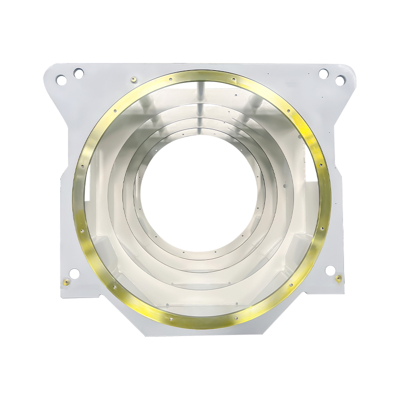
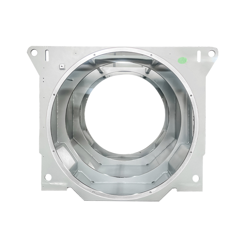
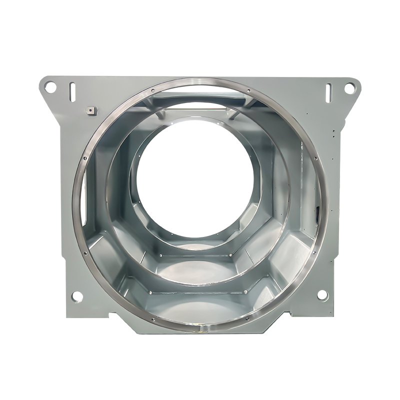
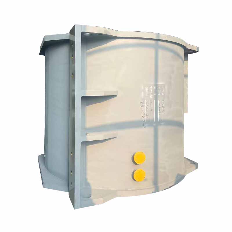
For custom drivetrain layouts, prototype turbines, and replacement frames where an exact casting pattern no longer exists, the industrial welded box-type motor base for heavy-duty applications offers a practical alternative to waiting for new casting tooling, with the added benefit of weight optimization through selective plate thickness and stiffening rib placement.
Alignment Precision: Why a Few Millimeters Define Generator Lifespan
Of the generator frame's three functional requirements, alignment maintenance is the one most directly linked to downstream maintenance costs and unplanned downtime. The connection between generator frame precision and drivetrain reliability is well-documented in wind turbine maintenance records, yet it remains underweighted in many component procurement decisions.
In a geared turbine, the generator's input shaft must be aligned with the gearbox output shaft within angular and parallel tolerances that are typically specified in the turbine's commissioning manual. Angular misalignment in the range of 0.1–0.3 mm/m and parallel offset above 0.05–0.1 mm are sufficient to generate bearing load patterns that deviate significantly from design intent. The output bearing of the gearbox and the input bearing of the generator are the components most immediately affected — both experience combined radial and axial loads that accelerate their wear rate when misalignment is present.
The generator frame is the primary structural determinant of whether specified alignment is achievable and maintainable. A frame whose mounting surface flatness deviates from specification forces the installation team to use shim stacks to compensate, which introduces its own risk of non-uniform contact and load concentration. A frame that was correctly flat at installation but deforms under thermal cycling or dynamic loading will allow alignment to drift during service, producing bearing wear that appears as an operational problem rather than as a structural one.
Face milling of generator mounting pads to flatness within 0.030 inches (approximately 0.75 mm) across the full bearing surface is an industry benchmark for nacelle bedplate and rear frame machining. For high-precision applications and direct-drive generators where air gap control is critical, tighter tolerances are routinely specified. This is why CNC machining of welded frame assemblies — not just fabrication — is a non-negotiable step in quality generator frame production.
Direct-Drive vs Geared Turbines: Different Frames for Different Demands
The global wind market's sustained shift toward direct-drive permanent magnet generators — now used in approximately 30% of installations and growing — has changed the structural brief for generator frames in ways that are not always reflected in specifications written around geared turbine assumptions.
In a geared turbine, the generator is a relatively compact high-speed machine. Its mass is modest, its output shaft connects to a flexible coupling that absorbs minor misalignment, and the gearbox acts as a structural intermediary that distributes some of the rotor loads before they reach the generator frame. The frame design task is demanding but relatively well-bounded.
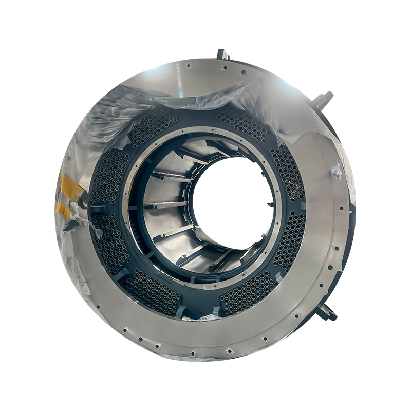
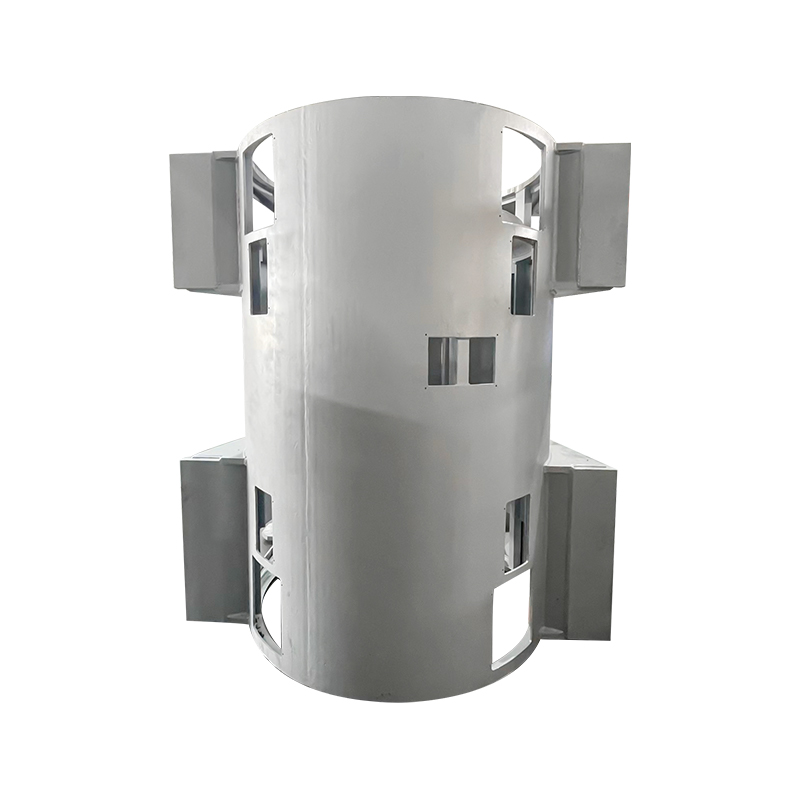
In a direct-drive turbine, the generator is large-diameter, low-speed, and heavy — often weighing two to three times the equivalent-rating geared generator. There is no gearbox to mediate between the rotor and the generator, so the full rotor thrust load, bending moment, and gyroscopic torque from blade weight asymmetry transmit directly into the generator structure and its supporting frame. The torque support function — preventing the stator casing from rotating under reaction torque — becomes structurally more demanding because the torque arm (generator radius) is large and the available structural depth of the frame is constrained by nacelle geometry. The square-base cylindrical motor frame designed for large wind power units addresses this by combining a stiff cylindrical outer shell with a square-section base that distributes reaction loads efficiently into the main frame connection interface.
Air gap control is a further complication specific to direct-drive designs. The radial gap between the permanent magnet rotor and the stator winding in a large direct-drive generator is typically 5–10 mm — narrow relative to the generator diameter. Any deflection of the frame that allows the generator axis to shift eccentrically produces magnetic pull forces that are self-amplifying: the rotor deflects toward the stator, the magnetic attraction increases, and the deflection increases further. Generator frames for direct-drive turbines must therefore be designed with stiffness targets that go beyond static load capacity to include deflection limits under the combined operational load case.
Manufacturing and Quality Standards for Wind Turbine Generator Frames
The engineering demands described above translate into specific manufacturing requirements that distinguish qualified wind turbine component suppliers from general fabricators.
Weld quality is foundational. Structural welds in generator frames are subject to cyclic loading over a design life of 20–25 years, which places them firmly in the fatigue-critical category. Full-penetration butt welds at primary load-carrying joints, combined with post-weld visual inspection and ultrasonic testing (UT) of all critical weld seams, are standard quality requirements. Weld procedure qualification to ISO 15614 or equivalent, along with certified welder qualifications to ISO 9606, provide the documented assurance that the welding process itself is under control.
CNC machining of mounting surfaces is the step that converts a fabricated structure into a precision component. Large-format machining centers operating on work envelopes of 8×4×2 meters or greater are required for utility-scale generator frames. Face milling of generator mounting pads, gearbox interface flanges, and main frame connection surfaces must achieve specified flatness and perpendicularity tolerances with reference to a common datum. Coordinate measuring machine (CMM) inspection of finished machined surfaces provides dimensional records that become part of the component's quality documentation package.
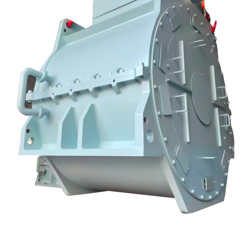
Quality management system certification — ISO 9001 as a baseline, IATF 16949 for manufacturers with automotive-adjacent production processes — provides the process control framework within which these manufacturing steps are executed consistently rather than on a best-effort basis. For wind turbine components that will operate unattended at height for two decades, process consistency is not a commercial differentiator; it is a technical prerequisite. The motor mounting base for wind turbine nacelle installations is produced within this quality management framework, with SPC (Statistical Process Control) and CMM inspection integrated into the production workflow to ensure that dimensional compliance is verified, not assumed.
As turbine ratings continue to scale and direct-drive architectures take a larger share of new installations, the engineering demands on generator frames will only intensify. Suppliers who combine structural design capability, precision welding, large-format CNC machining, and documented quality systems are positioned to meet those demands — not just for today's 5 MW onshore machines, but for the offshore platforms where tomorrow's 15 MW turbines will operate.
Your email address will not be published. Required fields are marked *



 Email: [email protected]
[email protected]
 Telephone/Phone:
+86-18861576796 +86-18261588866
Telephone/Phone:
+86-18861576796 +86-18261588866
+86-15305731515 +86-18861576796
Copyright © Wuxi New Ruichi Technology Co., Ltd. / Wuxi Cailiang Machinery Co., Ltd. All rights reserved.
Stator And Rotor Cores Manufacturers
