 en
en
 русский
 Deutsch
Motor Frame & Motor Housing: Materials, Standards, and Selection Guide
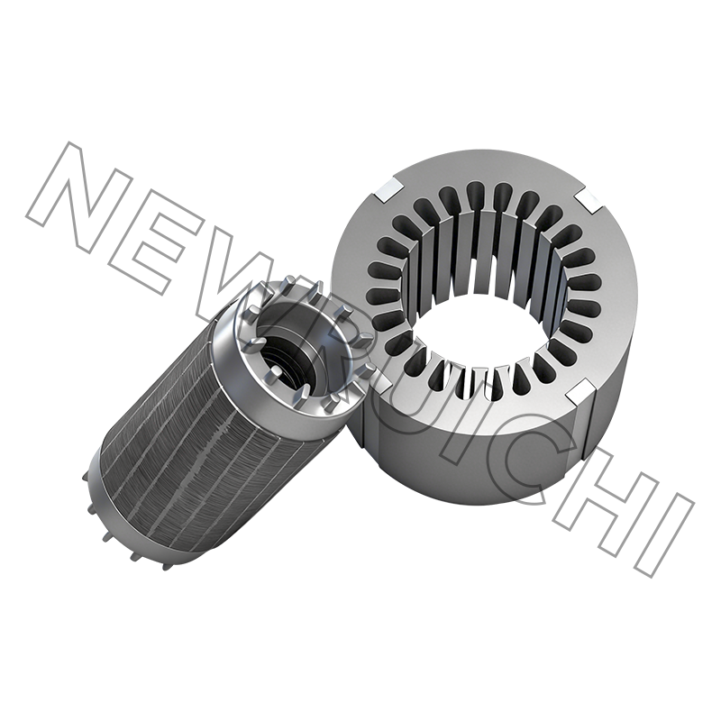
A motor's internal components — the stator, rotor, windings, and bearings — are precision-engineered to tight tolerances. Expose them to vibration, moisture, dust, or mechanical shock without the right enclosure, and they fail fast. The motor frame and motor housing are what stand between your drivetrain and the environment, and choosing the right one defines how long your equipment runs, how efficiently it dissipates heat, and whether it survives the conditions it was built for.
This guide breaks down the key factors in motor frame and housing selection: materials, manufacturing methods, industry standards, and application-specific demands — with a focus on the heavy-duty, large-frame segment where design decisions carry the most weight.
Content
- 1 What Is a Motor Frame and Why Does It Matter
- 2 Key Materials Used in Motor Frames and Housings
- 3 Motor Frame Standards: NEMA vs IEC
- 4 Manufacturing Processes: Die Casting, Sand Casting, and Welded Construction
- 5 Application-Specific Considerations: Wind Turbines, Industrial, and Marine
- 6 How to Choose the Right Motor Frame Supplier
What Is a Motor Frame and Why Does It Matter
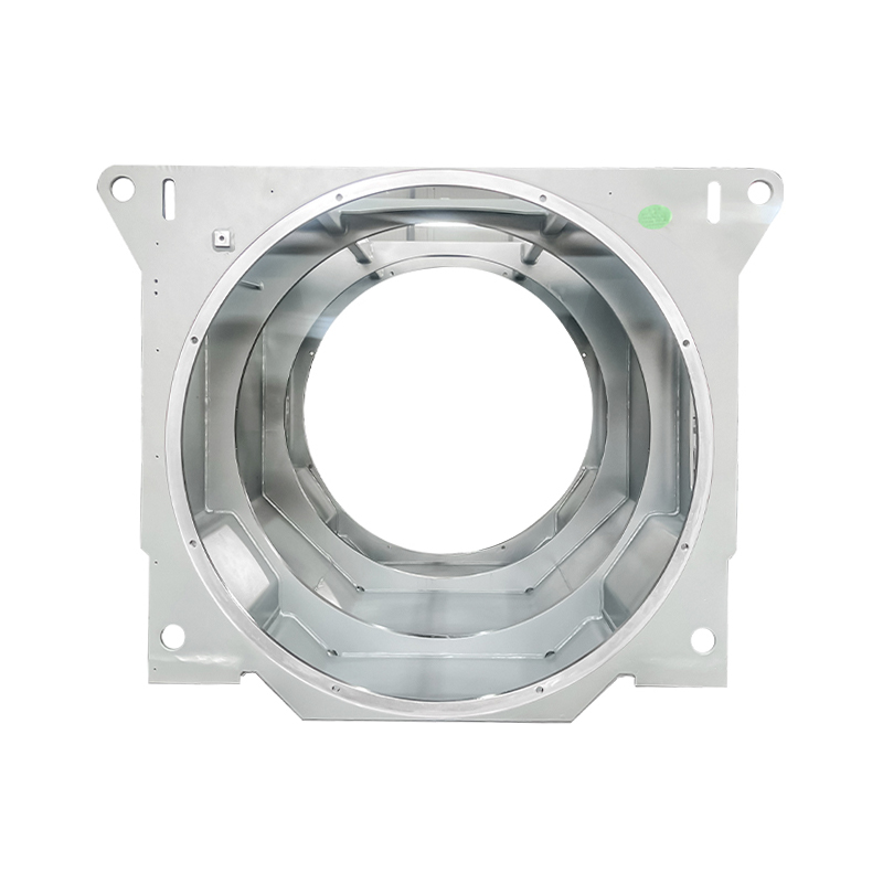
The terms "motor frame" and "motor housing" are often used interchangeably, but they describe related concepts. The motor frame refers to the outer structural body of the motor — it provides the mounting interface, sets shaft height, and defines the motor's footprint. The motor housing (or motor casing) is the enclosure that protects internal components and manages thermal and environmental exposure.
A well-designed motor housing does four things simultaneously: it absorbs and transmits mechanical loads, shields internal components from dust, moisture, and corrosive agents, facilitates heat dissipation through fins or cooling channels, and provides electrical insulation by preventing contact with live internal parts. In demanding industrial and energy applications, the housing is not a passive shell — it is a load-bearing, thermally active, environmentally sealed structure.
In practice, the housing design directly affects motor efficiency, service life, and maintenance intervals. Poor heat dissipation accelerates winding insulation breakdown. Inadequate sealing lets contaminants reach the bearings. Insufficient structural rigidity under cyclic loading leads to fatigue failures at mounting flanges. These are engineering problems, not assembly problems.
Key Materials Used in Motor Frames and Housings
Material selection is the first and most consequential decision in motor housing design. Each material class offers a different balance of strength, weight, thermal performance, corrosion resistance, and cost.
| Material | Strength | Weight | Thermal Conductivity | Corrosion Resistance | Best For |
|---|---|---|---|---|---|
| Cast Iron | High | Heavy | Moderate | Low (requires coating) | Heavy industrial, high-vibration environments |
| Aluminum Alloy (Die Cast) | Moderate | Light | Excellent | Good | Compact motors, EVs, heat-sensitive applications |
| Welded Steel (Fabricated) | Very High | Heavy | Good | Moderate (coating required) | Large-frame motors: wind turbines, marine, HV industrial |
| Stainless Steel | High | Heavy | Moderate | Excellent | Food processing, pharma, offshore, chemical environments |
Cast iron remains the standard for general-purpose industrial motors where weight is not a constraint. It machines well, dampens vibration effectively, and tolerates high mechanical stress. Its main limitation is susceptibility to corrosion without surface treatment.
Aluminum die casting dominates compact and medium-duty motor housings. Its thermal conductivity — roughly three times that of cast iron — makes it ideal where heat management is critical. It is the default choice in EV traction motors and servo motor applications where power density is high.
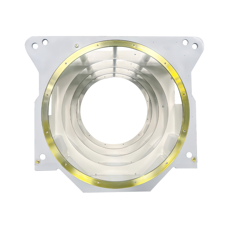
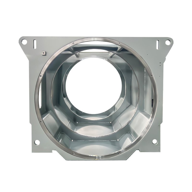
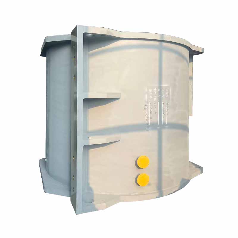
Welded steel construction occupies a different segment entirely. For large motors in the megawatt range — wind turbine generators, high-voltage industrial drives, marine propulsion systems — die casting tooling becomes impractical and cast iron becomes too heavy to handle. Welded box-type frames, fabricated from steel plate and structural sections, offer the dimensional flexibility, strength, and repairability that large-format applications demand. This is the construction method where precision fabrication and welding quality determine everything.
Motor Frame Standards: NEMA vs IEC
Two major standardization systems govern motor frame dimensions globally: NEMA (National Electrical Manufacturers Association), used primarily in North America, and IEC (International Electrotechnical Commission), used across Europe, Asia, and most international markets.
NEMA frame sizes use an alphanumeric designation — for example, 182T or 324T — where the first two digits encode the shaft height in sixteenths of an inch, and the letter suffix provides information on mounting configuration and shaft specifications. Standard integral horsepower NEMA frames run from 143T through 449T, covering motors in the 1–250 HP range. Beyond this, IEEE standards take over for larger industrial machines.
IEC frame sizes use a metric system based on shaft centerline height in millimeters. A frame size of IEC 160, for example, indicates an 160 mm shaft height. IEC designations follow the format: frame number + letter suffix indicating mounting type (B3 for foot-mounted, B5 for flange-mounted, etc.).
For procurement engineers, the practical implication is this: NEMA and IEC motors with the same power rating are not dimensionally interchangeable. Bolt patterns, shaft dimensions, and overall footprint differ. When specifying replacement or upgrade motors for international equipment, always confirm the frame standard and verify non-standardized dimensions (overall length, conduit box position) with the manufacturer — these are not regulated by either NEMA or IEC and vary between suppliers.
For very large motors — those used in wind turbines, high-voltage industrial drives, and marine systems — custom frame dimensions are engineered to project-specific requirements. Standardized frame tables do not apply at this scale; structural calculations and application-specific load cases drive the design.
Manufacturing Processes: Die Casting, Sand Casting, and Welded Construction
The manufacturing method for a motor housing is as consequential as the material. Each process has a defined envelope of part size, complexity, volume, and dimensional accuracy where it performs best.
High-pressure die casting is the dominant process for aluminum housings in the small-to-medium range. Cycle times are short, dimensional repeatability is excellent, and the process integrates cooling fins, mounting bosses, and complex internal geometries into a single shot. Tooling costs are substantial — typically $50,000 or more per die — so die casting is economically justified at volumes that amortize the tooling investment.
Sand casting and lost foam casting reduce tooling costs dramatically (as low as $2,000–$5,000 per mold) and accommodate larger, more complex geometries. They are the right choice for prototyping, custom large-frame housings, and lower-volume production runs where die tooling is not cost-effective. Dimensional accuracy is lower than die casting, with typical tolerances of ±0.3 mm, but this is adequate for most large motor applications.
Welded box-type construction is the method of choice for the largest motor frames — those used in multi-megawatt wind turbines, high-voltage industrial motors, and marine propulsion units. Steel plates are cut, formed, and welded into precise structural assemblies. This process handles virtually unlimited frame sizes, allows field repair and modification, and produces housings with very high structural integrity under cyclic loading. The critical quality variables are weld quality, dimensional accuracy after welding (thermal distortion control), and surface preparation for corrosion protection. Cailiang's manufacturing capabilities are specifically built around this process, with dedicated welding lines, post-weld machining, and quality control systems for large-frame motor housing production.
Application-Specific Considerations: Wind Turbines, Industrial, and Marine
Motor housing requirements change substantially depending on the operating environment. Three application segments stand out for their demanding and distinct requirements.
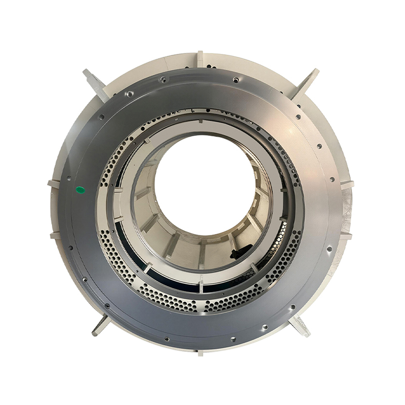
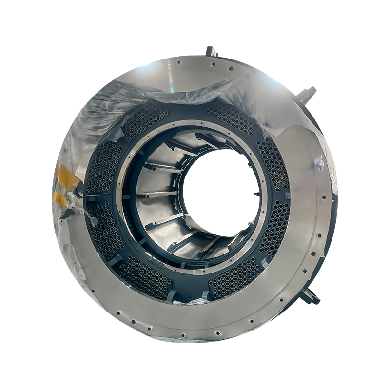
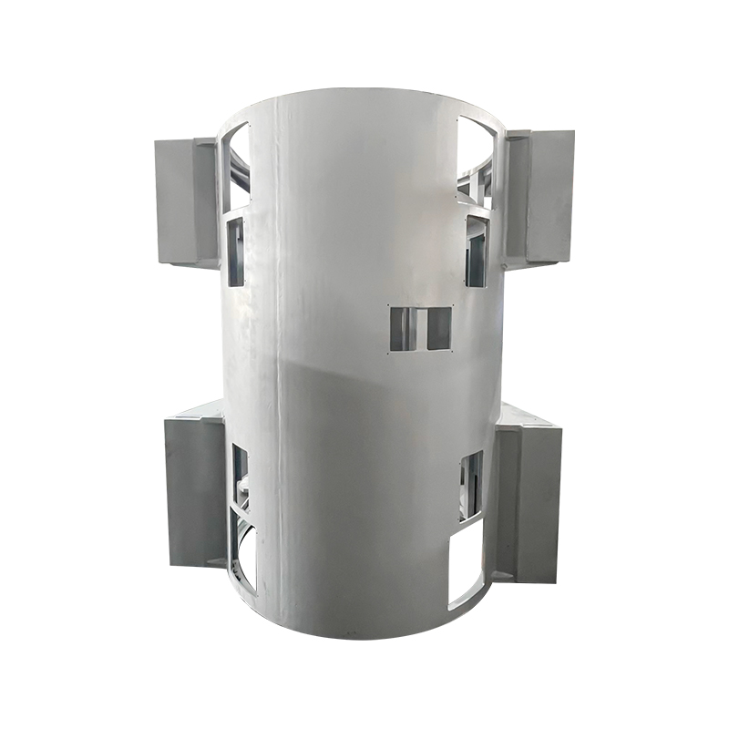
Wind Turbine Generator Housings
Wind turbine generators operate in remote, often offshore locations where maintenance access is infrequent and replacement logistics are expensive. The generator housing must withstand decades of cyclic mechanical loading from the rotor, temperature cycling from −30°C to +50°C, and corrosive exposure to salt air in coastal and offshore installations. Frame stiffness is critical: resonance between the housing natural frequency and rotor excitation frequencies can accelerate fatigue failure. Welded box-type motor housings for wind turbine generators are engineered to meet these structural and environmental demands, with corrosion protection systems and weld inspection protocols matched to the expected 20+ year service life.
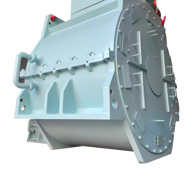
High-Voltage Industrial Motor Housings
Large industrial drives — compressors, pumps, extruders, mills — use motors in the hundreds to thousands of kilowatts, requiring housings that manage substantial radial and axial bearing loads, accommodate forced-air or water cooling systems, and meet IP protection ratings appropriate for the installation environment. Heavy-duty motor housings for high-voltage industrial applications must also meet international electrical safety standards, with earthing provisions, conduit entry configurations, and terminal box arrangements coordinated with the motor's electrical design.
Marine Motor Housings
Marine environments present the most aggressive corrosion conditions of any industrial application. Salt spray, humidity, and biological fouling attack unprotected steel surfaces continuously. Marine motor housings require base material selection and coating systems specifically qualified for saltwater exposure, and in many cases, stainless steel or hot-dip galvanized structural members for long-term protection. Vibration isolation is also more complex in marine installations, where ship structure-borne noise and hull vibration transmit into the motor mount. Corrosion-resistant motor housings designed for marine environments integrate these requirements from the structural design stage rather than applying them as afterthoughts.
How to Choose the Right Motor Frame Supplier
For standard small-to-medium frame motors, supplier selection is largely driven by price, lead time, and certification compliance. For large-frame and custom housing applications, the evaluation criteria shift toward engineering capability, manufacturing process control, and supply chain integration.
Key factors to evaluate in a large-frame motor housing supplier:
- Welding certification and process control: AWS or EN ISO welding procedure qualifications, qualified welder records, and documented non-destructive testing (NDT) programs are non-negotiable for structural housings in energy and marine applications.
- Post-weld machining capability: Bearing seats, end shield interfaces, and flange mounting faces require tight dimensional tolerances that can only be achieved through precision machining after welding. Without in-house machining, dimensional control is compromised.
- Surface treatment and corrosion protection: Blasting, priming, and topcoat systems should match the exposure category. Suppliers with in-house surface treatment control the process; those relying on subcontractors introduce a quality variable.
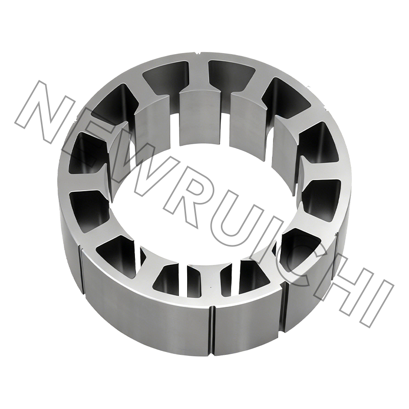
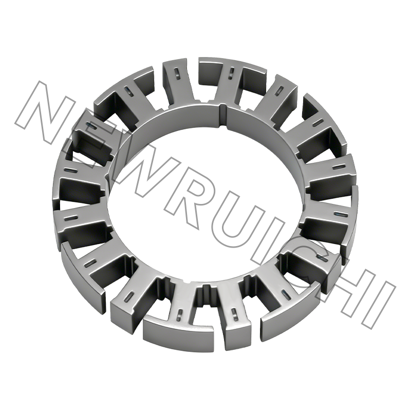
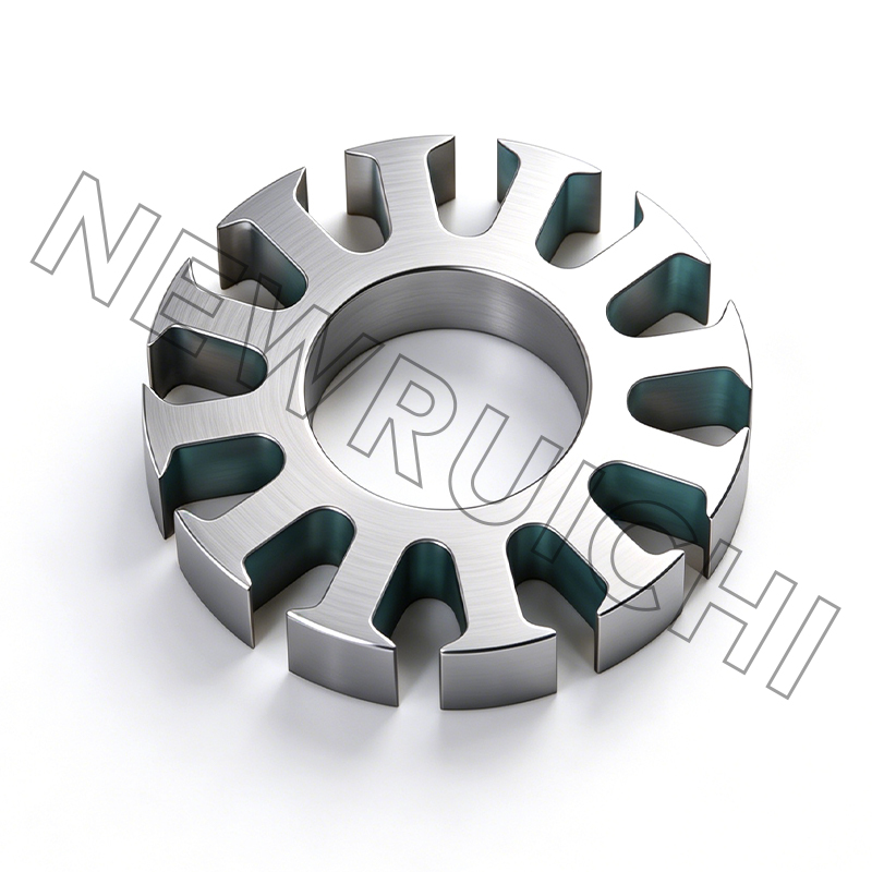
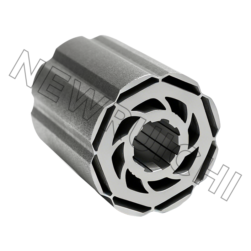
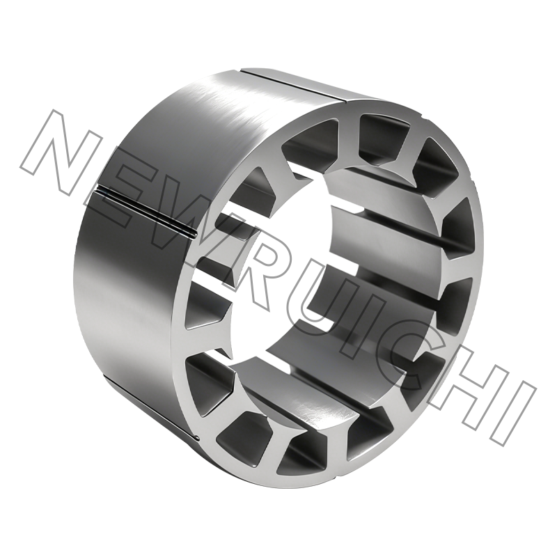
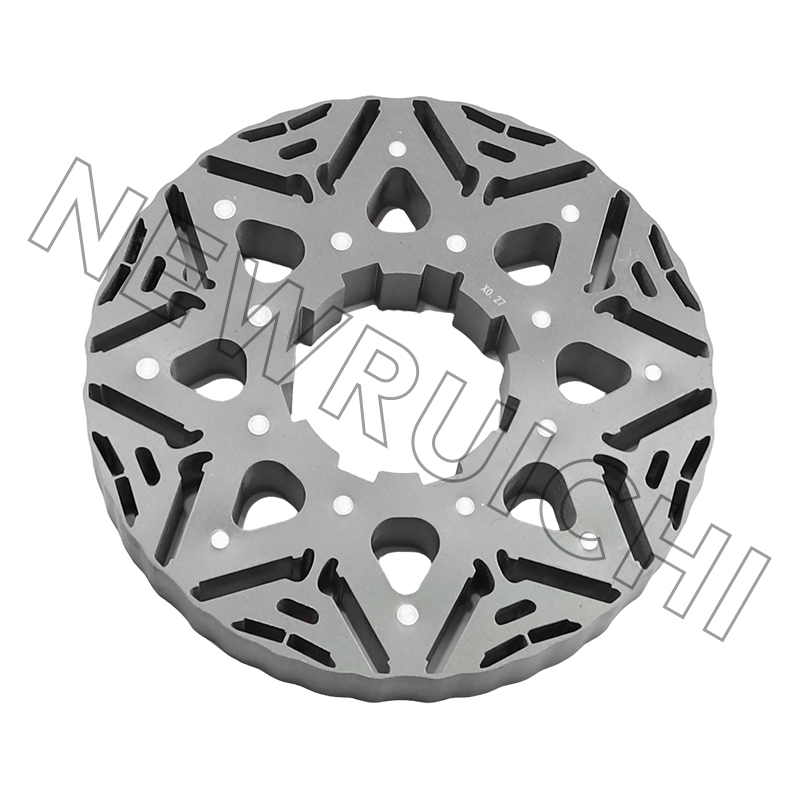
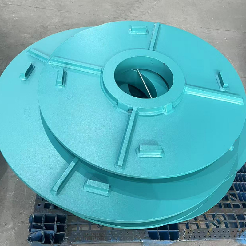
- Integrated supply capability: A supplier who manufactures both the motor housing and the precision motor stator and rotor cores eliminates interface risk between two of the motor's most critical components. Dimensional coordination between the core stack and the housing is a frequent source of assembly problems when these components come from separate suppliers.
- Quality system and certifications: ISO 9001 certification establishes a baseline. For marine and energy applications, class society approvals (DNV, BV, Lloyd's, etc.) provide additional assurance relevant to the end application.
The decision between a standard frame and a custom welded construction comes down to motor size, operating environment severity, and the cost consequence of unplanned downtime. For general industrial applications in the sub-100 kW range, catalogued cast or die-cast frames from certified manufacturers meet most requirements. For large-scale energy generation, high-voltage industrial drives, and marine propulsion, the engineering specificity of a custom welded housing is not optional — it is the design solution the application demands.
Your email address will not be published. Required fields are marked *


![]() Email: [email protected]
Email: [email protected]
[email protected]
[email protected]
![]() Telephone/Phone:
+86-18861576796 +86-18261588866
Telephone/Phone:
+86-18861576796 +86-18261588866
+86-15061854509 +86-15305731515
Copyright © Wuxi New Ruichi Technology Co., Ltd. / Wuxi Cailiang Machinery Co., Ltd. All rights reserved.
Stator And Rotor Cores Manufacturers
