 en
en
 русский
 Deutsch
Silicon Steel Transformer Core Buying Guide
Content
- 1 Why Core Material and Processing Define Transformer Performance
- 2 Oriented vs. Non-Oriented Silicon Steel: Choosing the Right Grade
- 3 How Precision Stamping Creates a High-Quality Transformer Lamination Core
- 4 The Role of Annealing in Achieving Low Core Loss
- 5 Performance Comparison: Core Loss by Material and Grade
- 6
- 7 Applications of Low Core Loss Silicon Steel Transformer Cores
- 8 Key Factors to Verify When Sourcing Silicon Steel Transformer Cores
Why Core Material and Processing Define Transformer Performance
In any transformer, the core is not merely a structural component—it is the magnetic engine that determines how efficiently electrical energy moves from primary to secondary winding. The choice of core material, grain orientation, lamination geometry, and post-processing treatment directly governs how much energy is lost as heat during operation, how much acoustic noise the unit generates under load, and how reliably the transformer performs over a service life that may span decades. For engineers specifying cores for power transformers, current transformers, reactors, and distribution equipment, understanding these variables is not academic—it translates directly into system efficiency, operating cost, and compliance with increasingly strict energy standards.
A silicon steel transformer core offers a combination of properties that no other commercially available material matches at scale: high magnetic permeability, controlled saturation flux density, low hysteresis loss, and the ability to be processed into precise lamination geometries. When manufactured with proper grain orientation and surface treatment, silicon steel cores consistently outperform alternatives in the power frequency range (50/60 Hz) that defines the vast majority of grid-connected electrical equipment.
Oriented vs. Non-Oriented Silicon Steel: Choosing the Right Grade
Silicon steel used in transformer cores is available in two fundamentally different microstructural forms, each suited to different applications. The distinction between them affects not only magnetic performance but also the manufacturing processes required to convert raw strip material into finished laminations.
Grain-Oriented Silicon Steel
Grain-oriented (GO) silicon steel is produced through a carefully controlled rolling and annealing sequence that aligns the magnetic domains of the material predominantly along the rolling direction. This alignment gives GO steel its defining characteristic: exceptionally low core loss and high permeability when the magnetic flux runs parallel to the rolling direction. In practice, this means GO steel delivers its best performance in transformer limbs and yokes where the flux path is well-defined and essentially unidirectional.
Modern high-permeability (HiB) grades of grain-oriented silicon steel achieve core losses as low as 0.85 W/kg at 1.7 T and 50 Hz, and permeability values that allow designers to reduce core cross-sections and overall transformer weight without sacrificing magnetic performance. These properties make GO silicon steel the material of choice for large power transformers, distribution transformers, and any application where no-load losses must be minimized to meet efficiency mandates such as EU Tier 2 or DOE standards.
Non-Oriented Silicon Steel
Non-oriented (NO) silicon steel has a more randomized grain structure, which gives it more uniform magnetic properties in all directions within the plane of the sheet. This isotropy makes it suitable for applications where the flux path changes direction—rotating machines, reactors with complex flux geometries, and certain current transformer designs. While NO steel has higher core losses than GO grades at the same induction level, its isotropic behavior simplifies core design in geometries where a single flux direction cannot be maintained throughout the entire magnetic circuit.
For reactor cores, where the flux path may pass through multiple limbs at varying angles, non-oriented silicon steel provides a practical balance of magnetic performance and manufacturing flexibility. It is also used extensively in current transformer cores where the toroidal or ring geometry means the flux travels around the circumference of the core rather than in a single linear direction.
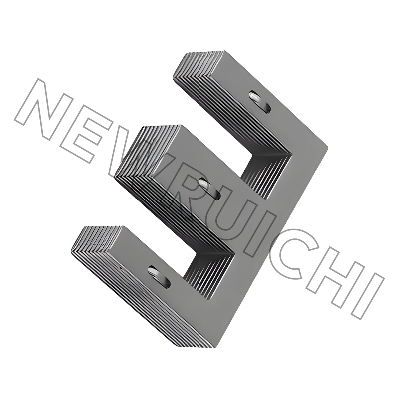
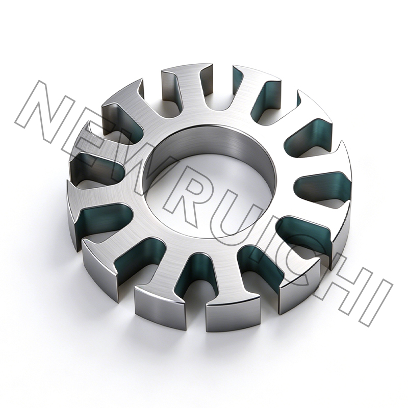
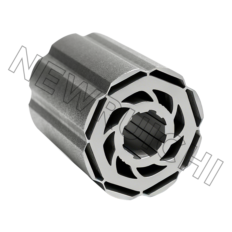
How Precision Stamping Creates a High-Quality Transformer Lamination Core
The path from silicon steel strip to finished transformer lamination core passes through several manufacturing stages, each of which has measurable consequences for the core's final magnetic and acoustic performance. Stamping—also called punching or blanking—is the process by which individual lamination shapes are cut from the rolled strip. The quality of this operation determines the dimensional accuracy of each lamination, the condition of the cut edges, and ultimately the uniformity of the assembled stack.
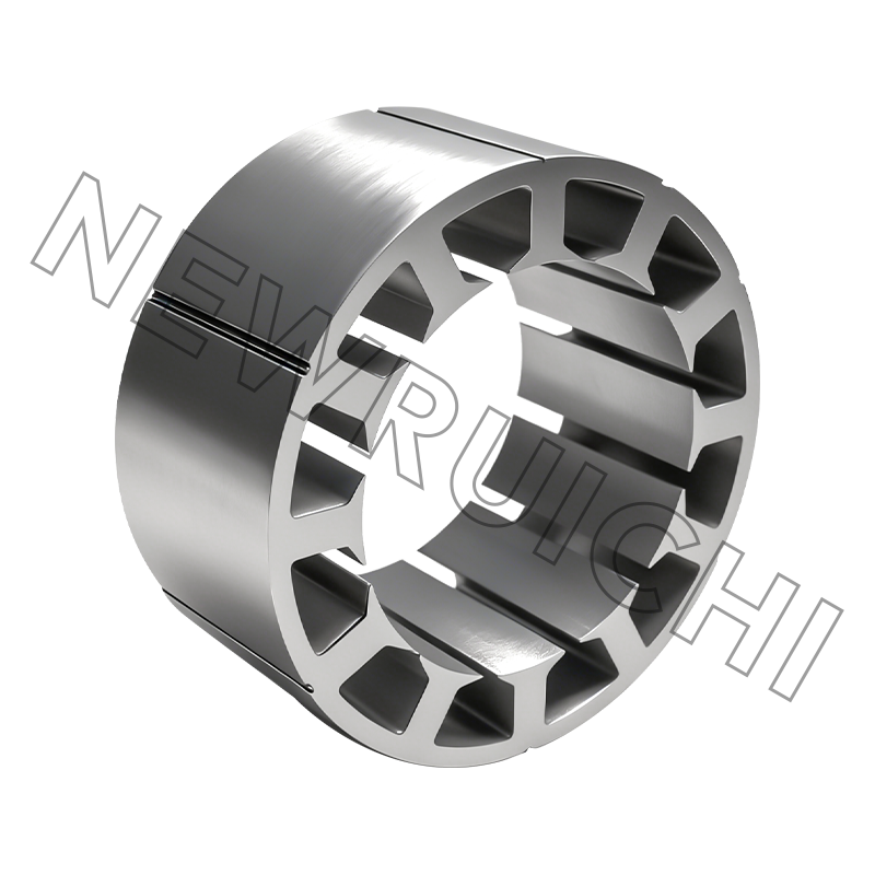
Precision stamping uses hardened die sets maintained to tight tolerances, typically holding dimensional accuracy within ±0.05 mm for critical features such as corner radii, slot widths, and step-lap joint angles. This level of precision matters because the joint regions of a lamination stack—where separate pieces of steel butt against or overlap each other—are the primary source of both elevated core loss and audible noise. Imprecise stamping creates gaps and misalignments at these joints, forcing the flux to cross air gaps and generating localized heating and magnetostrictive vibration.
Step-lap joint designs, in which successive lamination layers are offset by a fixed increment, distribute the joint reluctance over multiple layers and significantly reduce the flux density peaks that cause noise and loss. Achieving consistent step-lap geometry across a production run requires stamping tooling that maintains its accuracy over millions of cycles—a standard that separates precision lamination manufacturers from commodity suppliers.
The Role of Annealing in Achieving Low Core Loss
Stamping introduces plastic deformation into the silicon steel along the cut edges and in regions of the lamination that experience die contact. This deformation disrupts the grain structure of the material, creating residual stress that elevates hysteresis loss and reduces permeability in the affected zones. For thin laminations (0.23–0.35 mm), the proportion of the cross-section affected by edge damage can be significant, making stress relief a critical post-processing step.
Annealing addresses this by heating the stamped laminations to a temperature typically between 750°C and 850°C in a controlled atmosphere—usually nitrogen or hydrogen—for a defined dwell time, then cooling at a controlled rate. This thermal cycle allows the dislocated grain boundaries introduced by stamping to recover, restoring the magnetic properties of the steel close to its pre-stamping condition. In practice, properly annealed laminations show hysteresis loss reductions of 15–30% compared to unannealed parts, and a corresponding improvement in permeability that allows cores to operate at lower excitation current.
The annealing atmosphere is equally important. Oxygen contamination during annealing degrades the insulating coating on the lamination surface, increasing eddy current paths between layers and raising total core loss. Controlled atmosphere annealing in an inert or reducing gas environment preserves the inter-laminar insulation and maintains the full benefit of the stress relief treatment.
Performance Comparison: Core Loss by Material and Grade
The following table summarizes typical core loss values for common silicon steel grades used in transformer lamination core manufacturing, tested at 1.5 T and 50 Hz. These values represent the total specific core loss (W/kg) combining both hysteresis and eddy current components:
| Material Type | Grade Example | Thickness (mm) | Core Loss at 1.5T/50Hz (W/kg) | Typical Application |
| HiB Grain-Oriented | 27RGH095 | 0.27 | 0.95 | Large power transformer |
| Standard Grain-Oriented | 30Q120 | 0.30 | 1.20 | Distribution transformer |
| Non-Oriented (Low Loss) | 35WW250 | 0.35 | 2.50 | Reactor, current transformer |
| Non-Oriented (Standard) | 50W470 | 0.50 | 4.70 | Small transformer, relay |
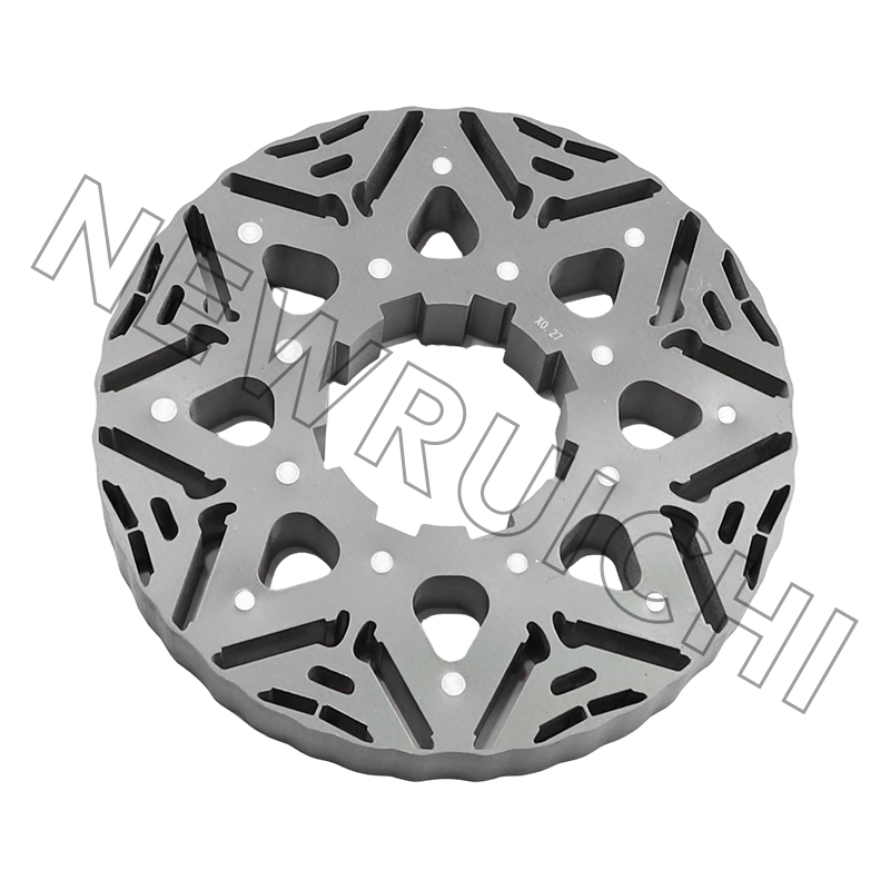
Applications of Low Core Loss Silicon Steel Transformer Cores
The demand for a low core loss silicon steel transformer core is driven by regulatory pressure, operating economics, and noise sensitivity—factors that vary in weight depending on the application but are present across all major sectors that use power conversion equipment.
- Power transmission and distribution transformers: No-load losses in distribution transformers run continuously for 8,760 hours per year regardless of load. A reduction of 0.1 W/kg in specific core loss across a population of transformers translates to measurable energy savings at the grid level, which is why efficiency tiers (IE1 through IE3 for distribution transformers) are becoming mandatory in major markets.
- Current transformers: Accuracy class compliance (IEC 61869) depends on the core's magnetic linearity and low excitation current. A transformer lamination core with high permeability and low hysteresis loss allows current transformers to maintain measurement accuracy across a wide primary current range without excessive secondary burden.
- Reactors and inductors: Air-gap reactors used in power factor correction, harmonic filtering, and variable frequency drives require cores that maintain stable permeability under DC bias and AC ripple simultaneously. Non-oriented silicon steel cores with controlled air gaps provide the inductance stability these applications demand.
- Noise-sensitive installations: Transformers installed in residential areas, hospitals, and data centers face strict acoustic emission limits. Low core loss materials inherently produce less magnetostrictive strain, and precision stamping with step-lap joints minimizes the mechanical excitation that converts this strain into audible sound.
Key Factors to Verify When Sourcing Silicon Steel Transformer Cores
When evaluating a transformer lamination core supplier, the following technical specifications should be confirmed with test data rather than accepted as nominal claims:
- Core loss test certificates: Ask for Epstein frame or single sheet tester (SST) measurements at the induction levels and frequencies relevant to your design, not only at the standard 1.5 T/50 Hz reference point.
- Lamination surface insulation resistance: Inter-laminar insulation coating integrity should be verified by Franklin tester or equivalent, with results reported in ohm·cm².
- Dimensional inspection reports: Critical dimensions—particularly joint gap, step-lap offset consistency, and lamination flatness—should be documented for each production batch.
- Annealing process documentation: Confirm that post-stamping annealing is performed in a controlled atmosphere and that temperature profiles are logged and traceable to each production lot.
- Material traceability: The silicon steel strip used should be traceable to a certified mill with documented magnetic properties per IEC 60404 or equivalent national standards.
For power transmission and distribution infrastructure, where transformer cores operate continuously for 30 or more years, specifying verified low core loss silicon steel transformer core components—backed by process documentation and independent test data—is the single most effective step a procurement team can take to reduce total life-cycle costs and meet grid efficiency targets.

Your email address will not be published. Required fields are marked *


![]() Email: [email protected]
Email: [email protected]
[email protected]
[email protected]
![]() Telephone/Phone:
+86-18861576796 +86-18261588866
Telephone/Phone:
+86-18861576796 +86-18261588866
+86-15061854509 +86-15305731515
Copyright © Wuxi New Ruichi Technology Co., Ltd. / Wuxi Cailiang Machinery Co., Ltd. All rights reserved.
Stator And Rotor Cores Manufacturers
