 en
en
 русский
 Deutsch
Silicon Steel Coils & Thermal Expansion Guide
Content
- 1 Why Thermal Expansion Is a Critical Variable in Silicon Steel Applications
- 2 How Silicon Content Modifies the Steel Coefficient of Thermal Expansion
- 3 Practical Consequences of Thermal Expansion in Lamination Stack Assembly
- 4 How Slitting and Cross-Cutting Precision Affects Thermal Performance of Silicon Steel Coils
- 5 Specifying Silicon Steel Coils for Thermally Demanding Applications
Why Thermal Expansion Is a Critical Variable in Silicon Steel Applications
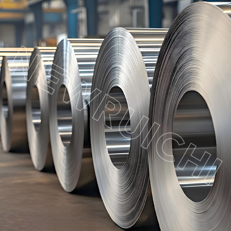
When engineers select materials for electric motor cores, transformer laminations, and generator stators, electromagnetic properties such as core loss and magnetic permeability dominate the conversation. Yet one mechanical property consistently determines whether a well-designed magnetic circuit performs reliably over its service life: the steel coefficient of thermal expansion. For silicon steel coils processed into lamination stacks, understanding thermal expansion is not a secondary concern — it is foundational to dimensional stability, assembly fit, and long-term electromagnetic consistency.
The coefficient of thermal expansion (CTE) describes how much a material expands or contracts per unit length for each degree of temperature change, expressed in units of μm/(m·°C) or 10⁻⁶/°C. For standard carbon steel, the CTE is approximately 11–12 × 10⁻⁶/°C. Silicon steel — iron alloyed with 1.5–4.5% silicon — exhibits a slightly lower CTE, typically in the range of 10–11.5 × 10⁻⁶/°C, depending on silicon content and grain orientation. This reduction, though modest in absolute terms, has measurable consequences when lamination stacks operate across wide temperature ranges, as is the case in traction motors for electric vehicles or large power transformers subject to load cycling.
How Silicon Content Modifies the Steel Coefficient of Thermal Expansion
Silicon additions to iron serve a dual purpose: they increase electrical resistivity (reducing eddy current losses) and alter the crystal lattice structure in ways that affect both magnetic anisotropy and thermal behavior. As silicon content increases from 1% to 4.5%, the CTE of the alloy decreases progressively. This occurs because silicon atoms, being smaller than iron atoms, distort the body-centered cubic (BCC) lattice and stiffen interatomic bonds, reducing the amplitude of thermally induced atomic vibration.
CTE Variation Across Silicon Steel Grades
| Material | Si Content (%) | CTE (×10⁻⁶/°C) | Typical Use |
|---|---|---|---|
| Low-carbon steel | 0 | 11.7–12.0 | General structural |
| Non-oriented silicon steel (low grade) | 1.5–2.5 | 11.0–11.5 | Small motors, ballasts |
| Non-oriented silicon steel (high grade) | 2.5–3.5 | 10.5–11.0 | EV traction motors, generators |
| Grain-oriented silicon steel (GO) | 3.0–3.5 | 10.0–10.8 | Power and distribution transformers |
| High-permeability GO (HiB) | 3.0–3.5 | 10.0–10.5 | Large power transformers |
The direction of measurement also matters for grain-oriented grades. Because the Goss texture aligns grains predominantly in the rolling direction, the CTE in the rolling direction and the transverse direction differ slightly — typically by 0.3–0.5 × 10⁻⁶/°C. This anisotropy must be accounted for when designing transformer cores assembled from strips cut at different angles, as differential expansion under load cycling can introduce interlaminar stress and accelerate insulation coating fatigue.
Practical Consequences of Thermal Expansion in Lamination Stack Assembly
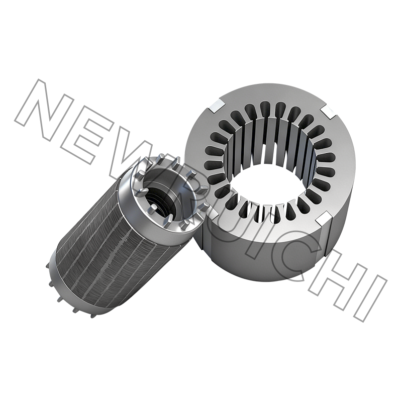
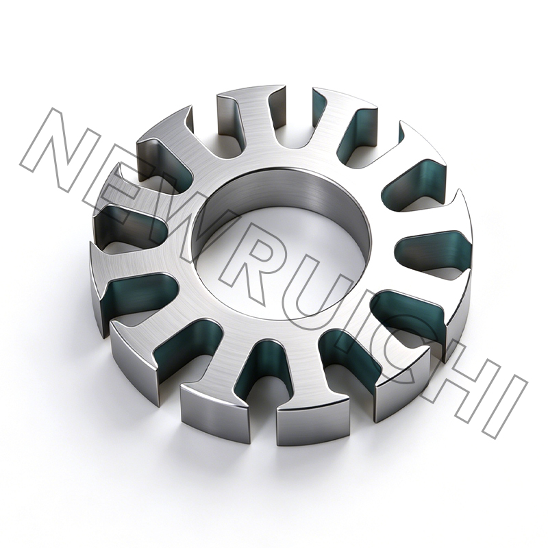
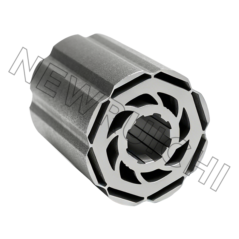
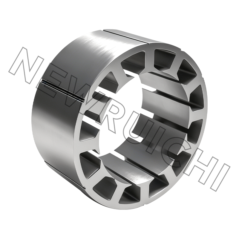
A lamination stack for a high-speed EV traction motor may contain 150–400 individual laminations, each punched from silicon steel coils and stacked with precision to form the stator or rotor core. During motor operation, resistive heating in the windings and core losses in the laminations raise the core temperature by 60–120 °C above ambient, depending on load and cooling system design. Over this temperature rise, each lamination expands according to the steel coefficient of thermal expansion, and the cumulative axial growth of the stack must be accommodated by the housing design.
For a 200 mm axial stack using silicon steel with a CTE of 10.8 × 10⁻⁶/°C and a temperature rise of 100 °C, the total axial expansion is approximately 0.216 mm. While this may seem negligible, it directly affects the interference fit between the lamination stack and the motor housing — a fit that must remain tight enough to prevent slip under torque while not imposing destructive hoop stress during thermal cycling. Engineers designing press-fit or shrink-fit assemblies must calculate the differential expansion between the silicon steel core and the aluminum or cast-iron housing (which has a significantly higher CTE of 21–24 × 10⁻⁶/°C for aluminum) to ensure the joint remains stable across the full operating temperature range.
Thermal Expansion Mismatch Between Core and Housing Materials
The CTE mismatch between silicon steel lamination stacks and aluminum motor housings is one of the most common sources of mechanical fatigue in EV drivetrain components. At operating temperature, the aluminum housing expands roughly twice as much as the silicon steel core, reducing the initial interference fit. If the initial press-fit is under-specified, the core can become loose at high temperatures, generating vibration, fretting wear, and ultimately noise that signals structural failure. Conversely, if the fit is over-specified to compensate for thermal relaxation, the hoop stress imposed on the silicon steel stack during assembly and at low temperatures may cause delamination or cracking at lamination edges. Accurate knowledge of the steel coefficient of thermal expansion for the specific silicon steel grade being used — not a generic steel value — is therefore essential input data for housing tolerance calculations.
How Slitting and Cross-Cutting Precision Affects Thermal Performance of Silicon Steel Coils
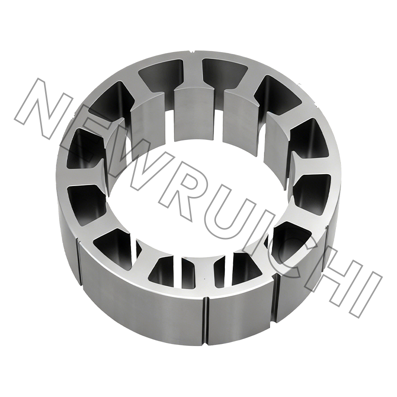
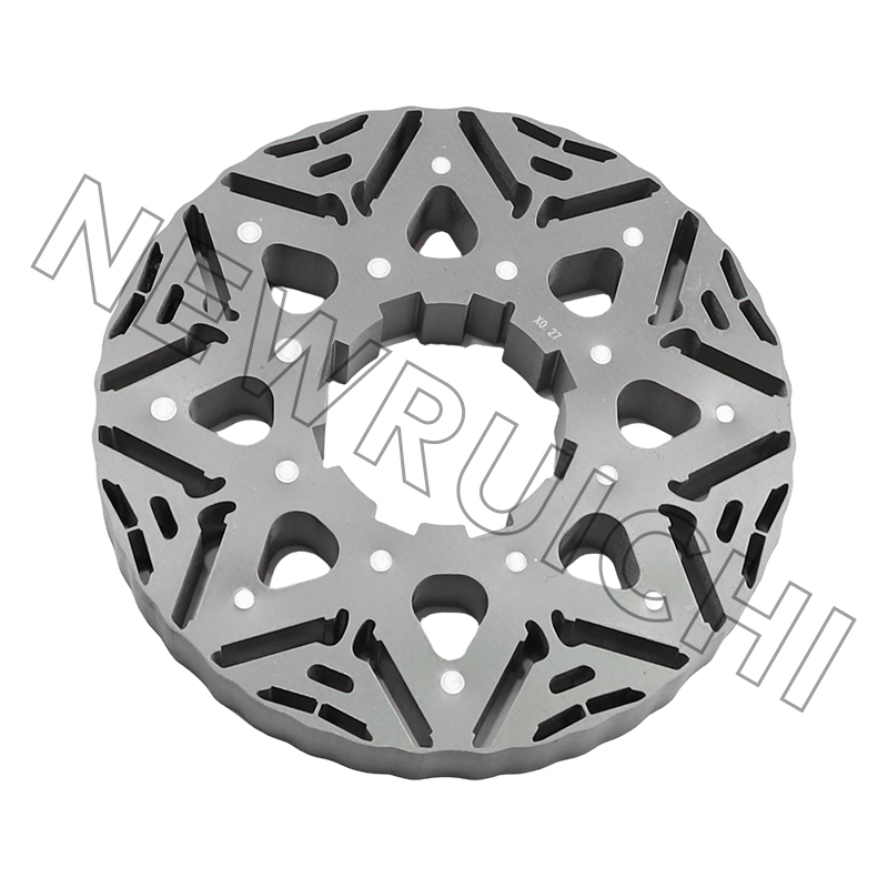
The quality of silicon steel coils as delivered from the slitting and cross-cutting process has a direct bearing on how lamination stacks behave thermally in service. Three specific quality attributes — flatness, edge condition, and residual stress — interact with thermal expansion to determine whether a stamped lamination maintains its intended geometry across the operating temperature range.
- Flatness and coil set: Silicon steel coils that carry excessive coil set (a persistent curvature from coiling) produce laminations that are not perfectly flat after blanking. When a lamination with residual bow is stacked and pressed into a core, interlaminar contact is non-uniform. During thermal cycling, differential expansion at contact and non-contact zones introduces microscopic relative movement that progressively degrades the insulation coating, increases core loss over time, and — in extreme cases — causes audible magnetostriction noise.
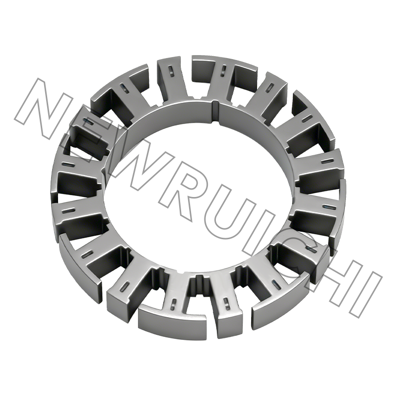
- Slit edge quality: Burr height on slit edges directly determines the interlaminar spacing within a stacked core. High burrs create localized air gaps that reduce effective stacking factor — the ratio of actual magnetic material to total stack volume. As the core heats and cools, thermally induced relative movement between laminations can cause burr tips to penetrate the insulation coating on adjacent laminations, creating electrical short circuits that dramatically increase eddy current losses and accelerate local heating.
- Residual stress from processing: Cold slitting and cross-cutting introduce residual tensile and compressive stresses at cut edges. These stresses alter local magnetic permeability (magnetoelastic effect) and interact with thermally induced stresses during operation to produce non-uniform flux distribution within the lamination. For high-frequency applications such as high-speed motors above 10,000 rpm, this non-uniformity measurably increases core loss and reduces efficiency.
Professional slitting operations address all three issues through precisely controlled blade clearance (typically 0.5–1.5% of material thickness), tension-leveling passes to correct coil set before slitting, and edge deburring where required. The result is silicon steel coils with consistent electromagnetic performance and flatness that translate directly into thermally stable, low-loss lamination stacks.
Specifying Silicon Steel Coils for Thermally Demanding Applications
When sourcing silicon steel coils for applications where thermal cycling is severe — EV traction motors, high-frequency inverter-driven motors, large power transformers, or industrial generators — the material specification should explicitly address both electromagnetic and thermal-mechanical requirements. Relying solely on grade designations (such as M270-35A or 35W250) without verifying the supplier's CTE data, insulation coating type, and processing quality can lead to field failures that are difficult to trace back to material root cause.
The following parameters should be confirmed with the silicon steel supplier before finalizing material selection for thermally demanding designs:
- Measured CTE value for the specific grade and thickness: Request test data, not handbook estimates, particularly for high-silicon grades where batch-to-batch silicon content variation can shift the steel coefficient of thermal expansion by 0.3–0.5 × 10⁻⁶/°C.
- Insulation coating thermal stability rating: C2, C3, C4, and C5 coatings differ in their resistance to stress relief annealing temperatures (typically 750–850 °C). If post-stamping annealing is part of the process, the coating must survive the thermal cycle without degrading adhesion or inter-laminar resistance.
- Flatness tolerance and stacking factor guarantee: For precision cores, specify maximum allowable bow per unit length and minimum stacking factor (e.g., ≥97%) to ensure thermally stable interlaminar contact across the stack.
- Slit width tolerance and burr height limit: Tight slit width tolerances (±0.05 mm or better) and maximum burr heights (typically ≤0.02 mm for thin gauges) are essential for maintaining consistent stacking and preventing coating damage during thermal cycling in service.
Working with a supplier who combines deep material knowledge with professional slitting and cross-cutting capabilities eliminates the gap between material certification and process-ready coil quality. When the steel coefficient of thermal expansion of your silicon steel is precisely known and your silicon steel coils are delivered with verified flatness and edge quality, thermal expansion becomes a manageable design variable rather than an unpredictable source of field failure.
Your email address will not be published. Required fields are marked *


![]() Email: [email protected]
Email: [email protected]
[email protected]
[email protected]
![]() Telephone/Phone:
+86-18861576796 +86-18261588866
Telephone/Phone:
+86-18861576796 +86-18261588866
+86-15061854509 +86-15305731515
Copyright © Wuxi New Ruichi Technology Co., Ltd. / Wuxi Cailiang Machinery Co., Ltd. All rights reserved.
Stator And Rotor Cores Manufacturers
