 en
en
 русский
 Deutsch
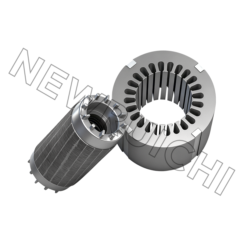
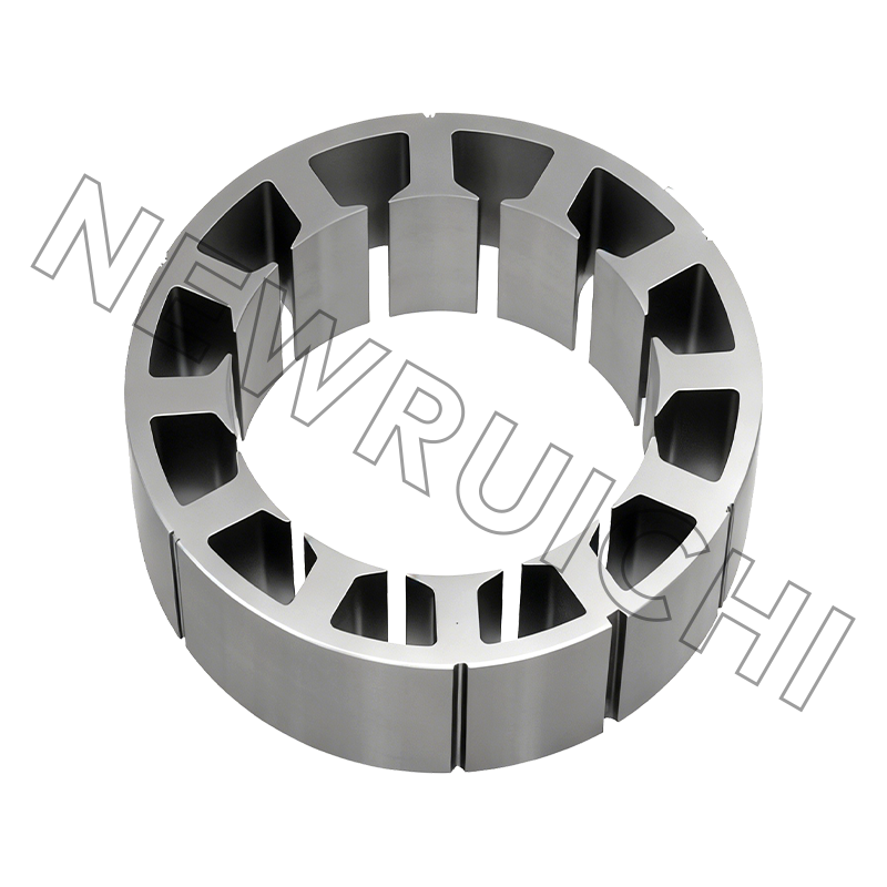
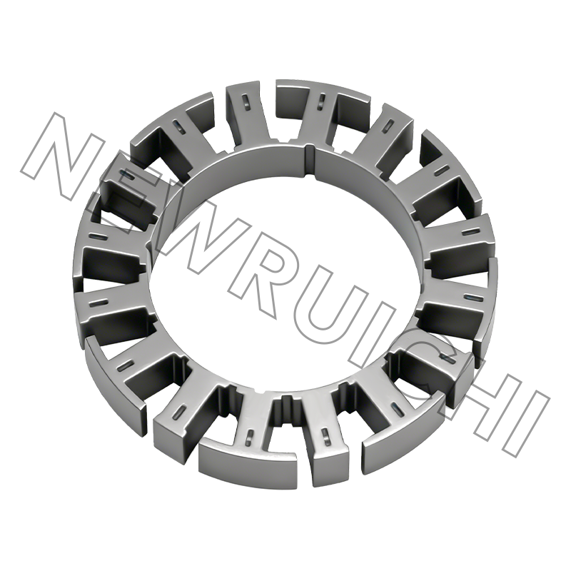
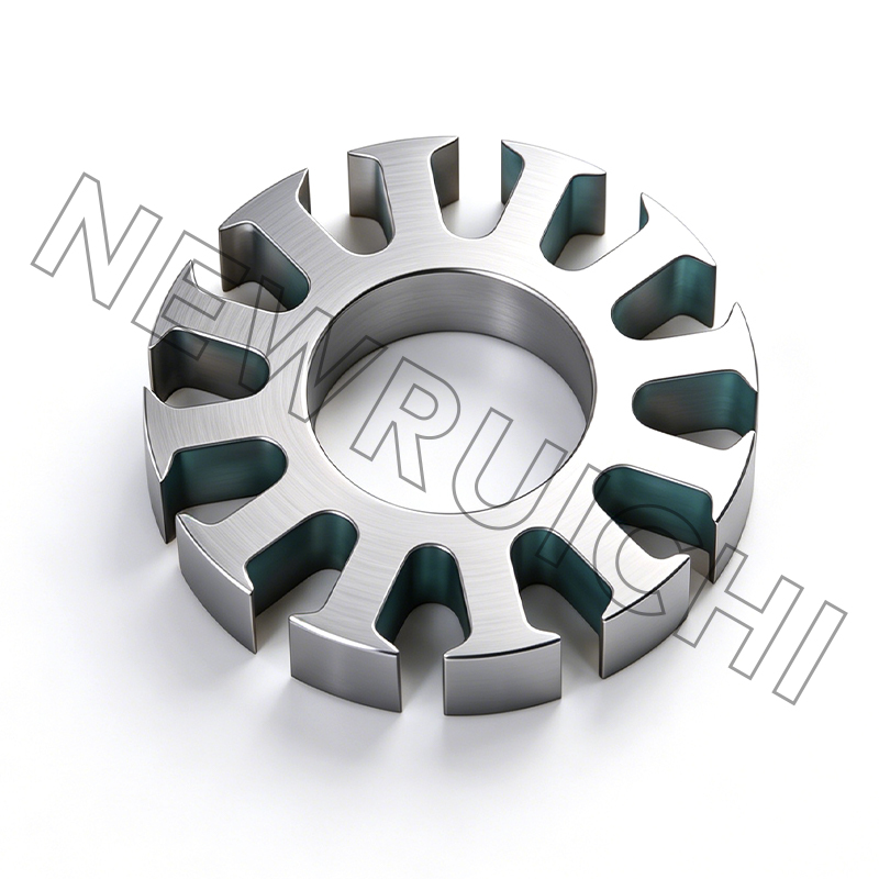
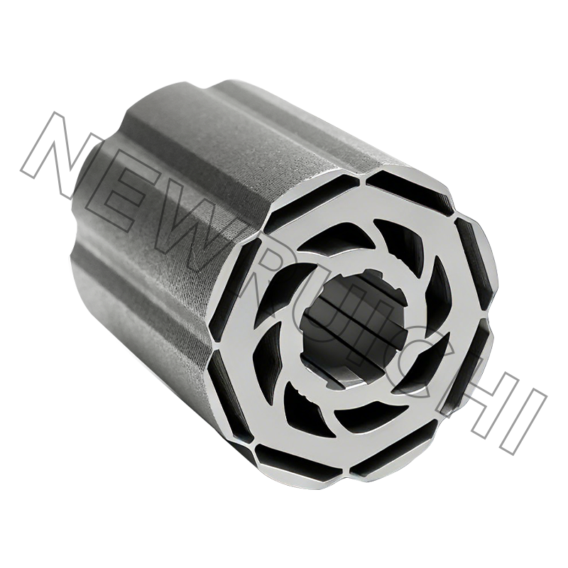
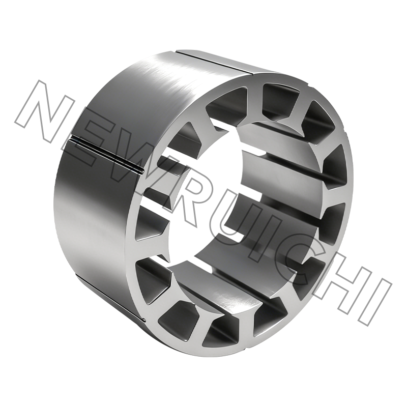
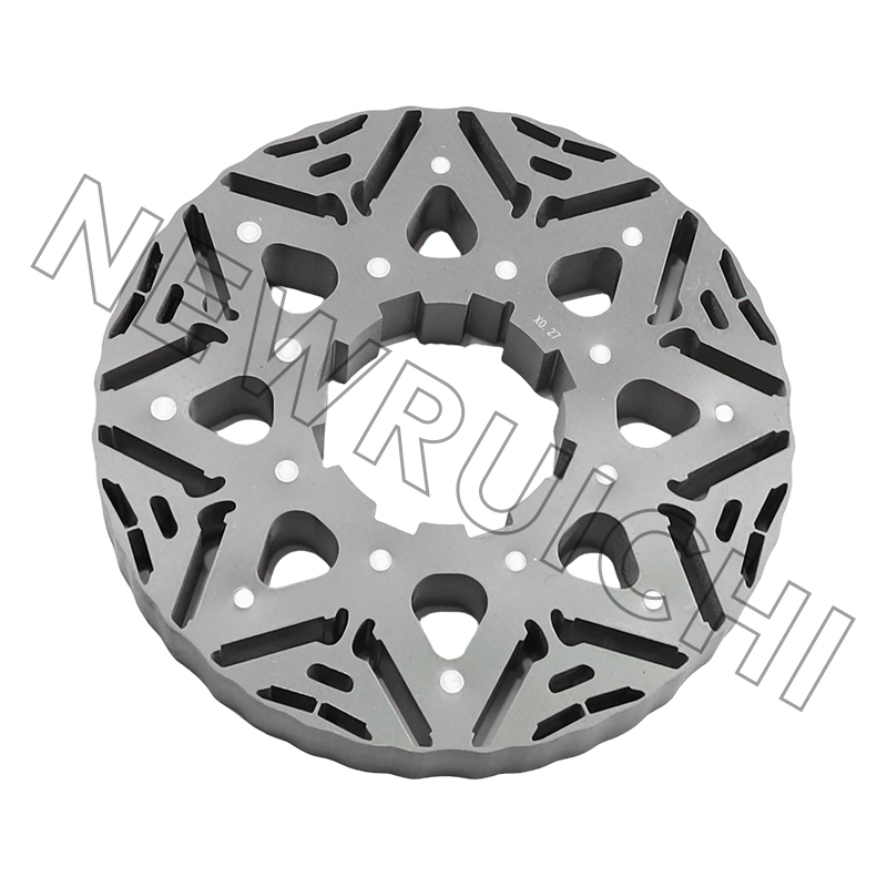
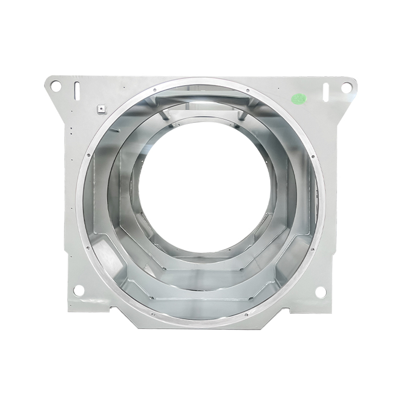
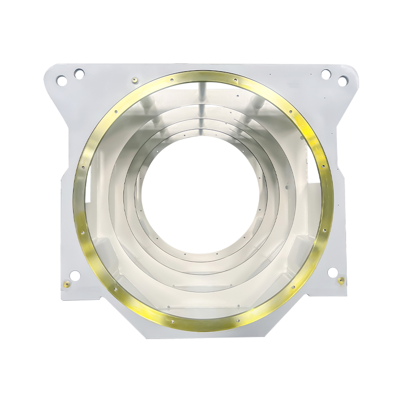
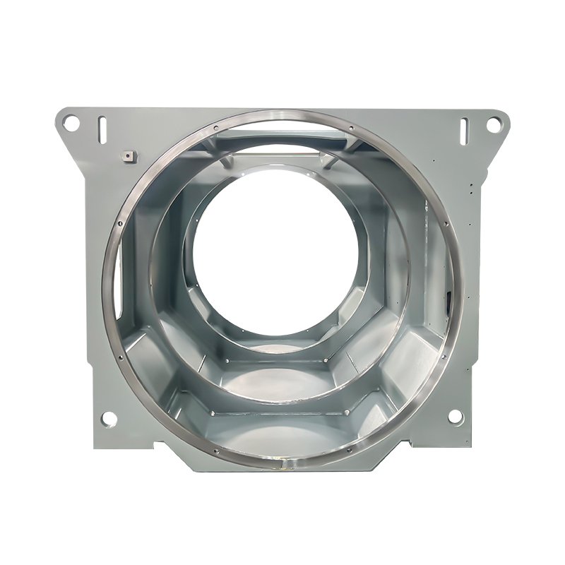
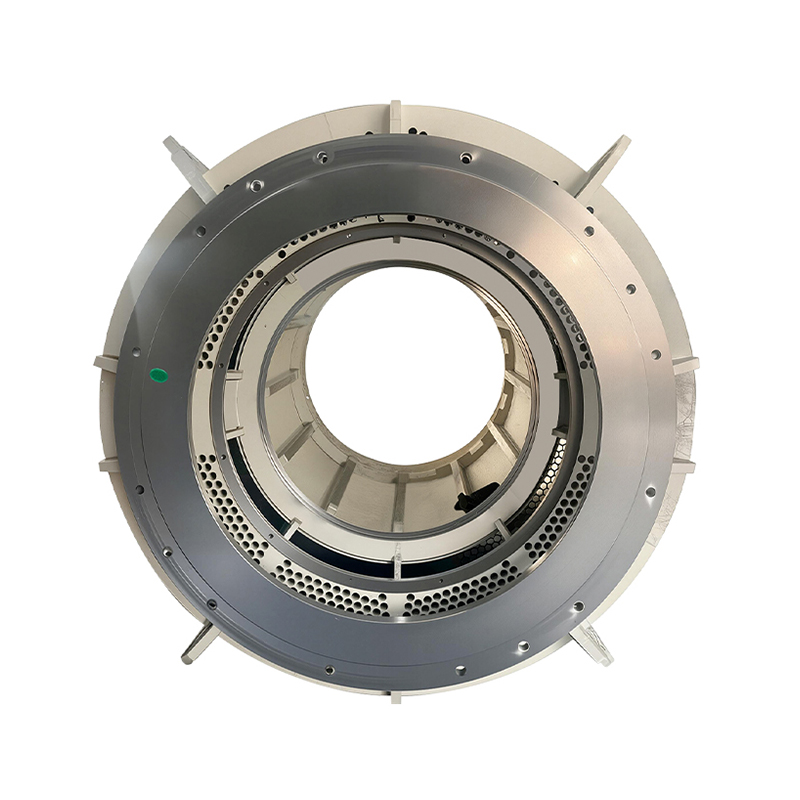
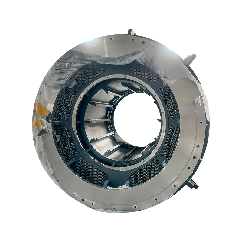
Motor Stator Core & Electric Motor Laminations Explained
New ruichi Products


Cailiang Products
![]() Email: [email protected]
Email: [email protected]
[email protected]
![]() Telephone/Phone:
+86-18861576796 +86-18261588866
Telephone/Phone:
+86-18861576796 +86-18261588866
+86-15305731515 +86-18861576796
Copyright © Wuxi New Ruichi Technology Co., Ltd. / Wuxi Cailiang Machinery Co., Ltd. All rights reserved.
Stator And Rotor Cores Manufacturers
