 en
en
 русский
 Deutsch
Motor Power Factor: Definition, Calculation, and How Motor Cores Affect It
Content
What Motor Power Factor Actually Measures
When a three-phase motor consumes 75 kW of real power at 400 V, the line current depends on its power factor. At 0.85 PF, that current is about 127 A. At 0.80 PF, the same 75 kW requires 135 A — six percent more current for no additional shaft output. The ratio behind this difference, real power in kilowatts divided by apparent power in kilovolt-amperes, is the motor power factor. For an AC motor it equals cos φ, the cosine of the phase angle between voltage and current.
Motors always run with a PF below 1 because they need magnetizing current to build the magnetic field in the stator and rotor cores before torque can be produced. This reactive component does no mechanical work, yet it travels through the windings, the supply cables, and upstream transformers. It is an unavoidable part of induction motor operation, but it is also influenced by design and materials.
How to Calculate Motor Power Factor
The calculation is straightforward: PF = real power (kW) / apparent power (kVA). For a three-phase motor, apparent power is S = 1.732 × V × I / 1000, where V is line-to-line voltage and I is line current.
Using the example above, a motor drawing 135 A at 400 V has an apparent power of 1.732 × 400 × 135 / 1000 = 93.5 kVA. With 75 kW of measured real power, its power factor is 75 / 93.5 = 0.80. If the same machine could hold 0.90 PF, the current for the same real power would fall to about 120 A.
| Quantity | Symbol | Unit | What it represents |
|---|---|---|---|
| Real (active) power | P | kW | Mechanical output plus losses; performs useful work |
| Reactive power | Q | kVAr | Energy stored and released to build the magnetic field in the core |
| Apparent power | S | kVA | Total power drawn from the supply; S² = P² + Q² |
The three quantities form a right triangle: S² = P² + Q². Reactive power Q is the portion the motor spends on magnetizing its magnetic circuit. At partial load, real power drops faster than magnetizing current, so PF falls sharply. A motor nameplated at 0.86 PF can easily measure 0.55–0.65 at half load.
Typical Motor Power Factor Values
Nameplate PF is a full-load value. Site measurements reflect the actual operating load, which is why real-world numbers are often lower. The table below gives indicative full-load ranges for standard low-voltage three-phase induction motors.
| Motor rating (kW) | Typical PF at full load | Typical PF at no load |
|---|---|---|
| 0.75 | 0.75–0.80 | 0.10–0.20 |
| 3.7 | 0.80–0.85 | 0.10–0.20 |
| 15 | 0.83–0.87 | 0.10–0.20 |
| 37 | 0.85–0.89 | 0.10–0.20 |
| 75 | 0.86–0.90 | 0.15–0.25 |
| 150 | 0.88–0.92 | 0.15–0.25 |
Two patterns matter when specifying motors. First, larger motors reach higher PF because magnetizing current and fixed losses make up a smaller share of total input. Second, slower machines — 6-pole and 8-pole designs — develop lower PF than comparable 2-pole or 4-pole motors because additional poles require more magnetizing ampere-turns. The same logic applies to oversizing: a 75 kW motor running at 20 kW shows a much lower PF than a correctly sized 22 kW motor doing the same job.
How the Motor Core Influences Power Factor
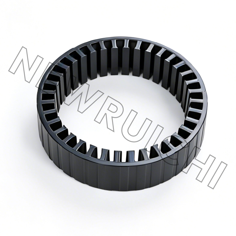
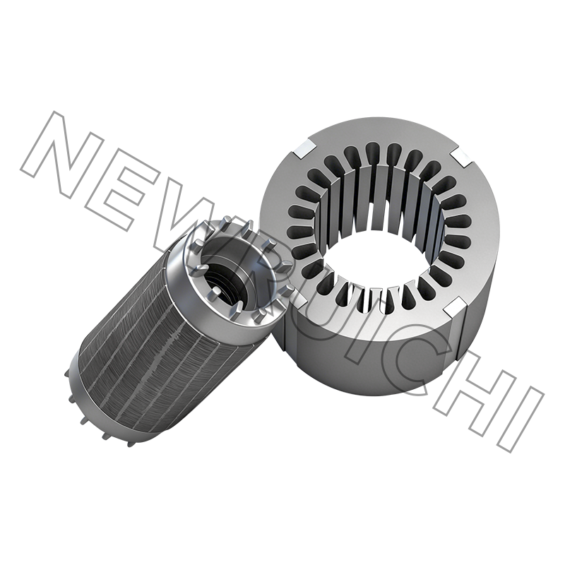
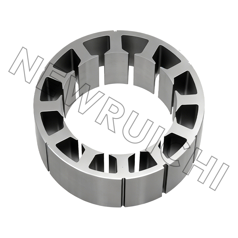
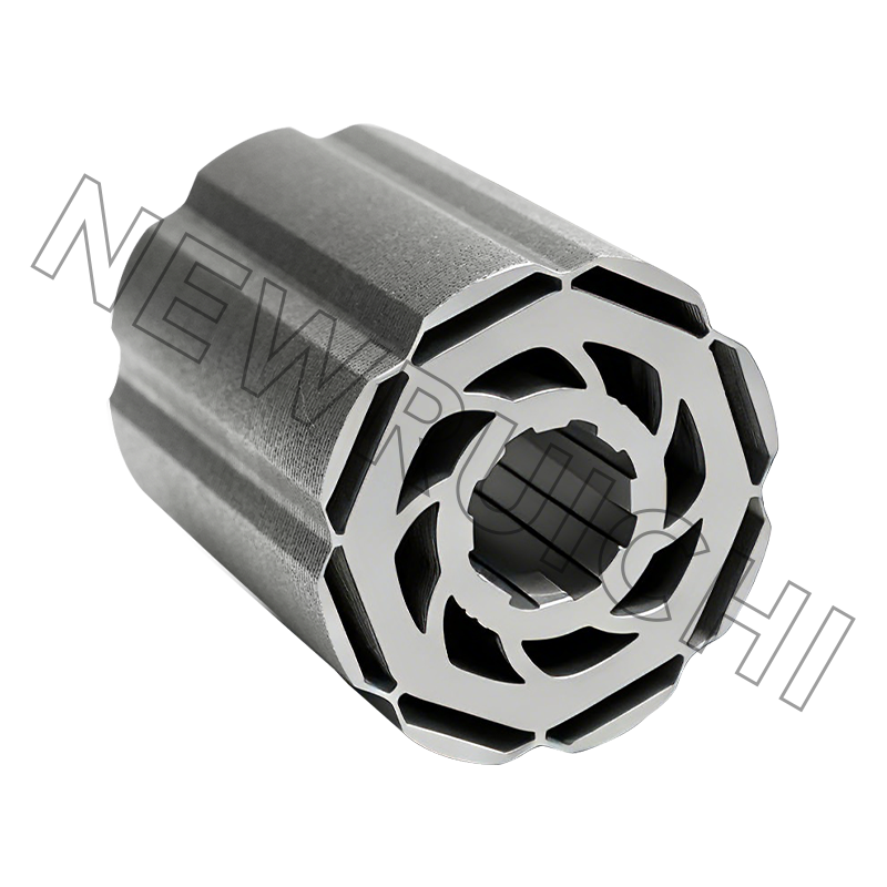
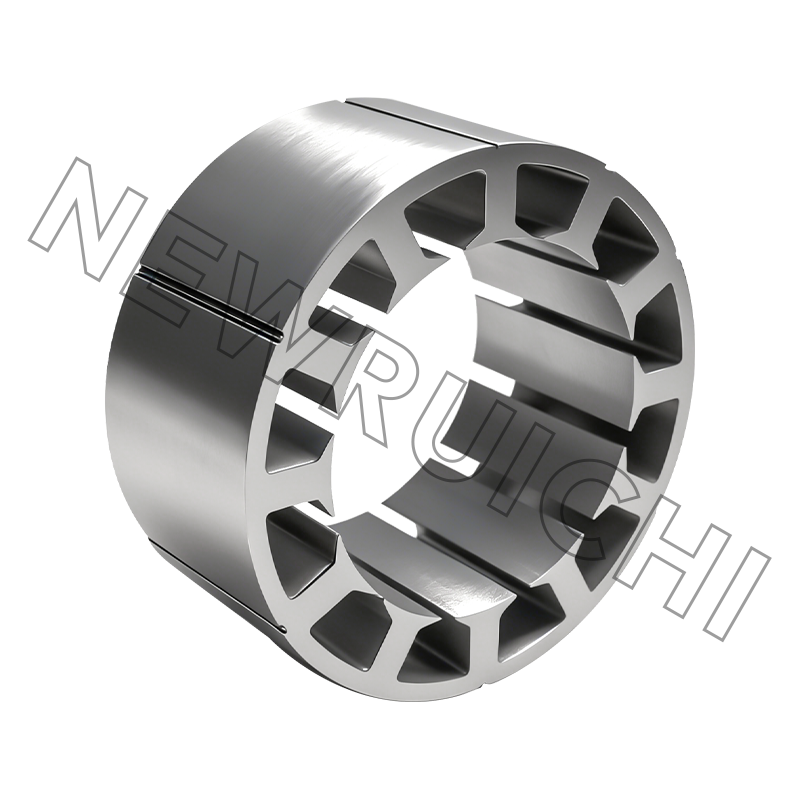
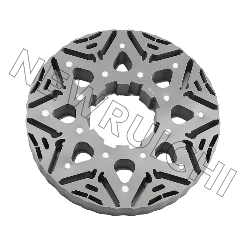
Power factor is not determined by the winding alone. The largest influence on reactive current is the motor's magnetic circuit — the stator and rotor cores. Core material, lamination thickness, and assembly method control how much magnetizing current the winding must supply and how much energy the iron loses in the process. A closer look at the structure of a motor core makes the connection clear.
Silicon Steel Grade and Core Loss
The grade of electrical steel sets both permeability and core loss. A higher grade of non-grain-oriented (NGO) silicon steel reduces hysteresis and eddy-current losses in the stator and rotor. Lower iron losses mean less input current is consumed by magnetizing and loss currents, which supports a higher PF under load. Material choice has a direct, measurable effect on the reactive power a motor draws.
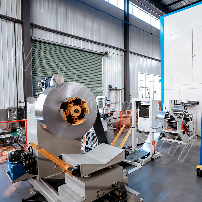 High Grade Non-grain-oriented (NGO) Silicon Steel Suppliers, Company - Wuxi New As High Grade Non-grain-oriented (NGO) Silicon Steel Suppliers and Company in China, New Ruichi/Cailiang offer Wholesale High Grade Non-g...View Product →
Lamination Thickness and Insulation
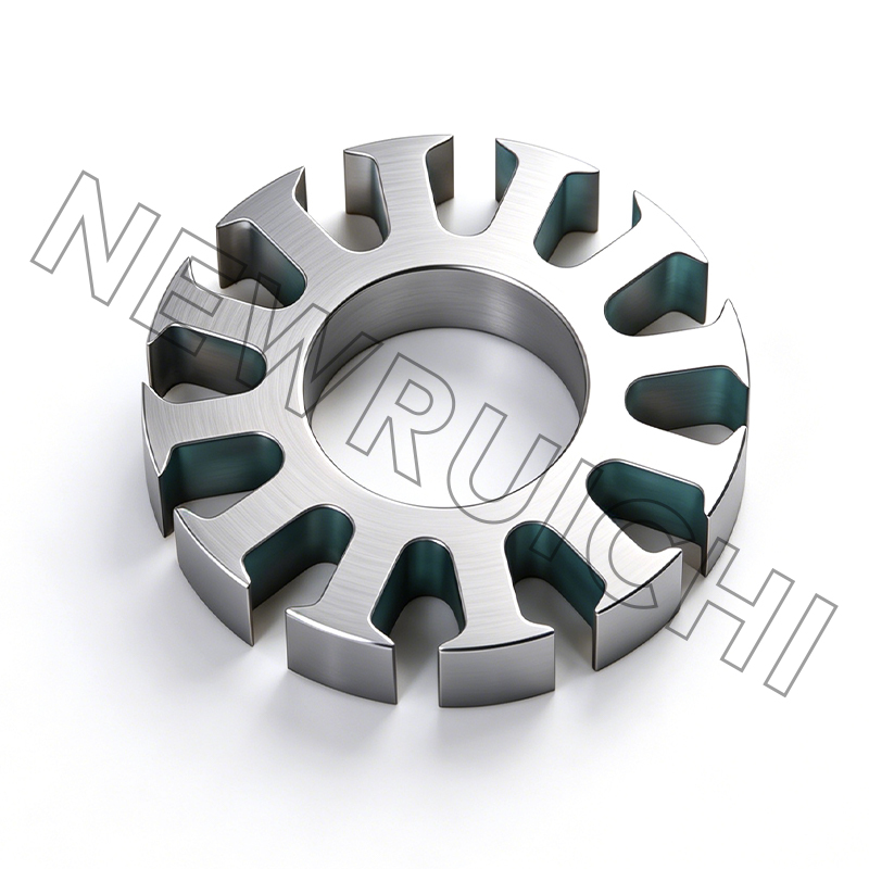
Motor cores are stamped from electrical steel sheets, typically 0.35–0.50 mm thick. Thinner laminations reduce eddy currents but raise processing cost. The insulation coating between laminations matters just as much: if adjacent sheets touch, circulating currents develop and losses climb. That is why AC motor stator and rotor laminations require controlled coating, accurate punching, and tight burr control throughout a production run.
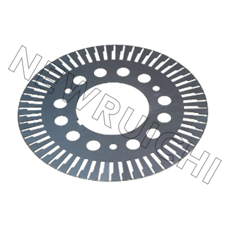 AC Motor Stator and Rotor Laminations Suppliers, Company - Wuxi New Ruichi TechnAs AC Motor Stator and Rotor Laminations Suppliers and Company in China, New Ruichi/Cailiang offer Wholesale AC Motor Stator and Rotor La...View Product →
Core Assembly Method
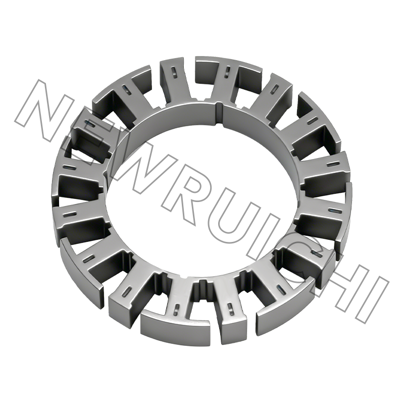
The way laminations become a finished stack changes the magnetic path. Interlocked cores are economical and dimensionally stable, but every interlock feature creates localized stress and some electrical shorting between layers. Welded cores are mechanically strong, yet each weld bead is a potential conductive bridge across the lamination stack, so weld position and length must be tightly managed. When these details are controlled, laser/TIG-welded laminated cores preserve layer insulation and keep losses low. The performance difference is large enough that many motor makers now buy finished motor core assemblies instead of loose laminations.
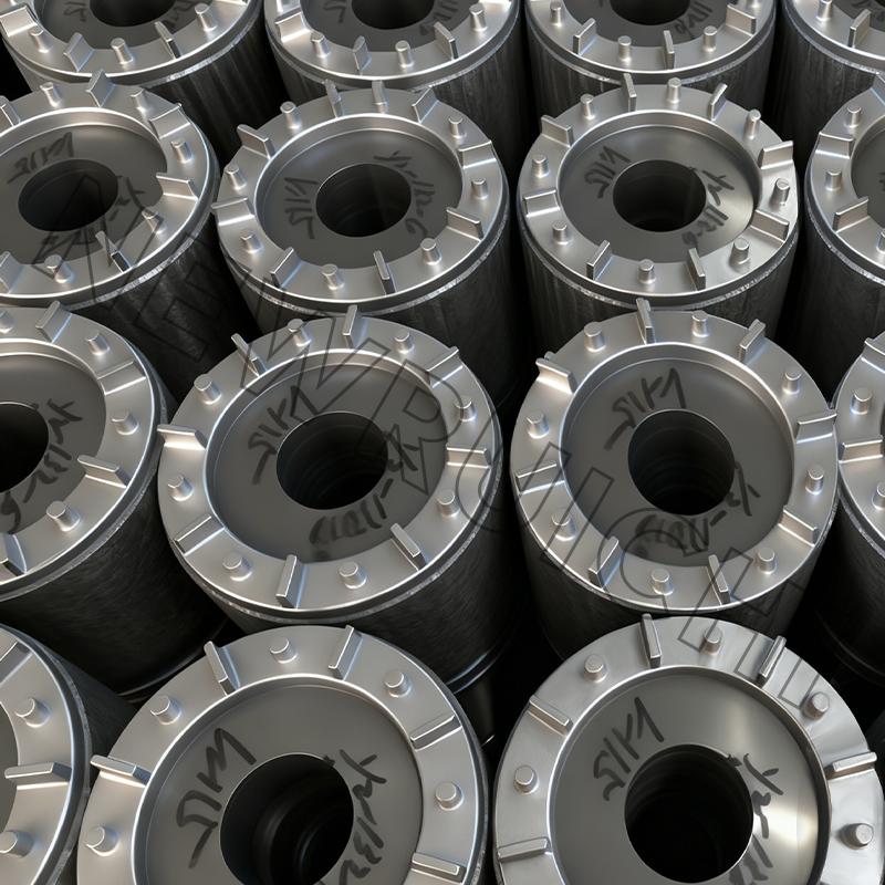 Laser/TIG-welded Laminated Core Suppliers, Company - Wuxi New Ruichi Technology As Laser/TIG-welded Laminated Core Suppliers and Company in China, New Ruichi/Cailiang offer Wholesale Laser/TIG-welded Laminated Core on...View Product →
Why a Low Motor Power Factor Costs More Than You Think
Low PF does not reduce mechanical output, but it raises every cost associated with delivering the same kilowatts:
- Higher line current, so cables, breakers, and transformers must be oversized.
- Greater I²R losses in every series element between the utility meter and the motor.
- Larger voltage drops, which lower motor torque and increase slip.
- Utility demand charges or PF penalties, commonly triggered below 0.90 or 0.95.
The arithmetic is easy to check. A 75 kW load at 400 V draws about 127 A at 0.85 PF. At 0.80 PF the current reaches 135 A, roughly 6% higher; at 0.70 PF it reaches 155 A, about 22% higher. That extra current heats cables and windings, causes voltage drop, and forces upstream equipment to be derated. The same load improved from 0.85 PF to 0.95 PF cuts apparent power demand from 88 kVA to 79 kVA — a 10% reduction in the billing quantity many utilities use for commercial and industrial accounts.
Power Factor Correction Options and Limits
Capacitors are the standard correction device. They supply leading reactive power that offsets the motor's lagging magnetizing current, and they can be installed at the motor terminals, on the distribution board, or centrally at the substation. The right level depends on where the reactive demand is created.
Variable frequency drives (VFDs) change the picture. The DC link inside the drive supplies reactive energy internally, so the grid-side PF of a VFD-fed motor is typically above 0.95 even when the motor itself runs at low PF. For fixed-speed motors, capacitor sizing needs caution. Over-correcting into a leading PF raises terminal voltage and creates switching transients, relay misoperation, and capacitor failures. A correction target around 0.92–0.95 is usually safer than trying to reach unity.
Harmonics add another constraint. VFDs and other non-linear loads produce distortion power factor, which capacitors cannot correct. In some cases capacitor banks resonate with transformer inductance at harmonic frequencies and amplify the distortion instead of reducing it. A basic power quality measurement prevents the most common mistakes.
Correction at the meter treats the symptom, not the cause. A motor whose core carries high losses or excessive magnetizing current keeps drawing reactive current regardless of how much capacitance is installed. Changing the core material and assembly method at the design or rebuild stage reduces reactive demand at its source. That is why OEMs and motor repair shops evaluate the manufacturing capabilities of their core supplier as part of the efficiency picture.
What Buyers and Designers Should Check
Before adding capacitors, measure the operating PF under real load instead of trusting the nameplate. Record voltage and current, estimate shaft load, and compare the result with the motor's full-load behavior. The exercise often reveals problems such as oversizing or high-loss cores that capacitors would otherwise hide.
- Confirm the operating PF under actual load; nameplate values are full-load values.
- Ask for the silicon steel grade and lamination thickness specified for the core.
- Choose the core assembly method — adhesive bonding, interlocking, or laser/TIG welding — based on the motor's target efficiency and PF.
- Match motor size to duty. An oversized motor running lightly loaded suffers low PF and low efficiency for its entire operating life.
Motor power factor is more than a billing detail. It reflects how effectively the motor's magnetic circuit converts incoming current into torque. When the core is built from the right silicon steel grade, lamination thickness, and assembly process, the motor simply needs less reactive current. That difference is measurable in the meter room — and it starts on the production line of the core supplier.
Your email address will not be published. Required fields are marked *


 Email: [email protected]
[email protected]
 Telephone/Phone:
+86-18861576796 +86-18261588866
Telephone/Phone:
+86-18861576796 +86-18261588866
+86-15305731515 +86-18861576796
Copyright © Wuxi New Ruichi Technology Co., Ltd. / Wuxi Cailiang Machinery Co., Ltd. All rights reserved.
Stator And Rotor Cores Manufacturers
