 en
en
 русский
 Deutsch
Motor Core and Motor Stator Core Guide: Materials, Manufacturing and Industry Applications
Content
- 1 What Is a Motor Core and Why Does It Matter?
- 2 Types of Motors and Their Core Requirements
- 3 Motor Stator Core: Structure, Function, and Manufacturing
- 4 Silicon Steel Lamination Grades and Their Performance Impact
- 5 Industry Applications Spanning Energy and Heavy Industry
- 6 Evaluating Motor Core Quality: Key Parameters to Specify
What Is a Motor Core and Why Does It Matter?
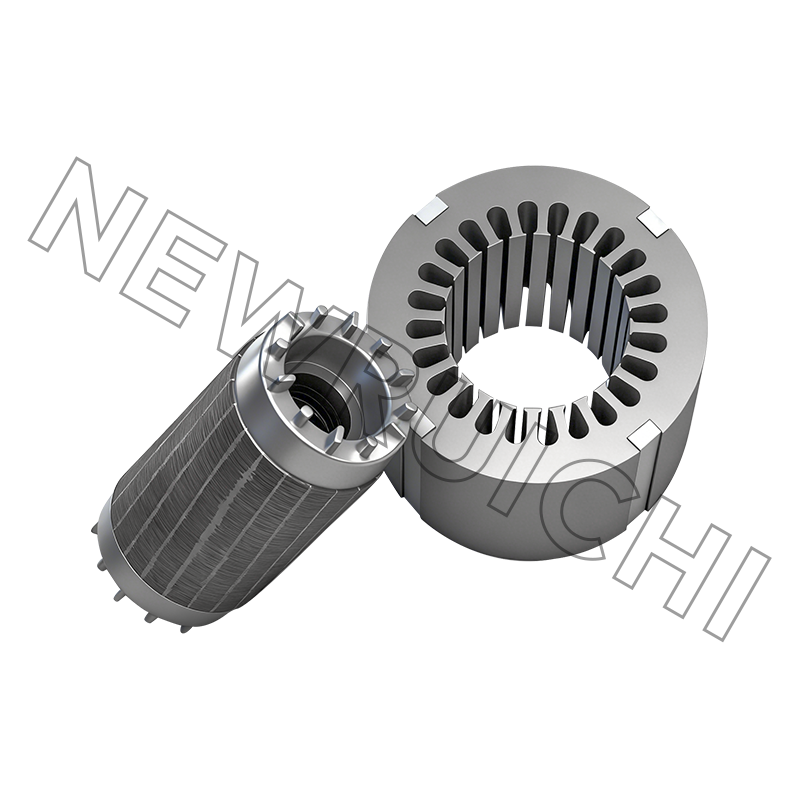
The motor core is the electromagnetic heart of every electric motor. It serves as the primary pathway for magnetic flux, concentrating and directing the magnetic field generated by the windings to produce the rotational force that drives mechanical output. Without a properly engineered motor core, the efficiency of energy conversion from electrical to mechanical power drops sharply, iron losses increase, and heat generation rises — all of which reduce the operating life and performance reliability of the motor system. As the core of an electric motor, its material composition, lamination geometry, stacking precision, and surface insulation quality collectively determine how much of the input electrical energy is converted into useful mechanical work and how much is lost as heat.
Modern motor cores are manufactured from silicon steel laminations — thin sheets of iron alloyed with silicon to increase electrical resistivity and reduce eddy current losses. Each lamination is produced with consistent electromagnetic performance and precise mechanical quality, then stacked and bonded or interlocked to form the complete core structure. The thickness of individual laminations typically ranges from 0.20 mm to 0.65 mm depending on the motor's operating frequency: thinner laminations are used in high-frequency applications such as new energy vehicle drive motors, while thicker grades suit lower-frequency industrial motors where core loss at the fundamental frequency is the primary concern.
Types of Motors and Their Core Requirements
Understanding the different types of motors in commercial use is essential for appreciating why motor core design varies so substantially across applications. Each motor topology places different demands on the core in terms of flux density, loss characteristics, mechanical dimensions, and thermal management. The major types of motors encountered across industrial, energy, and consumer applications include induction motors, permanent magnet synchronous motors, brushless DC motors, switched reluctance motors, and synchronous reluctance motors.
Induction Motors
Induction motors are the most widely deployed type among all types of motors in industrial drive systems, powering pumps, fans, compressors, conveyors, and machine tools globally. The stator core of an induction motor carries alternating flux at the supply frequency, making core loss — the sum of hysteresis loss and eddy current loss — a direct determinant of steady-state efficiency. Premium efficiency induction motors use thinner, higher-grade silicon steel laminations with tighter stacking tolerances to minimize these losses, enabling IE3 and IE4 efficiency classifications that reduce energy consumption and operating costs over the motor's service life.
Permanent Magnet Synchronous Motors
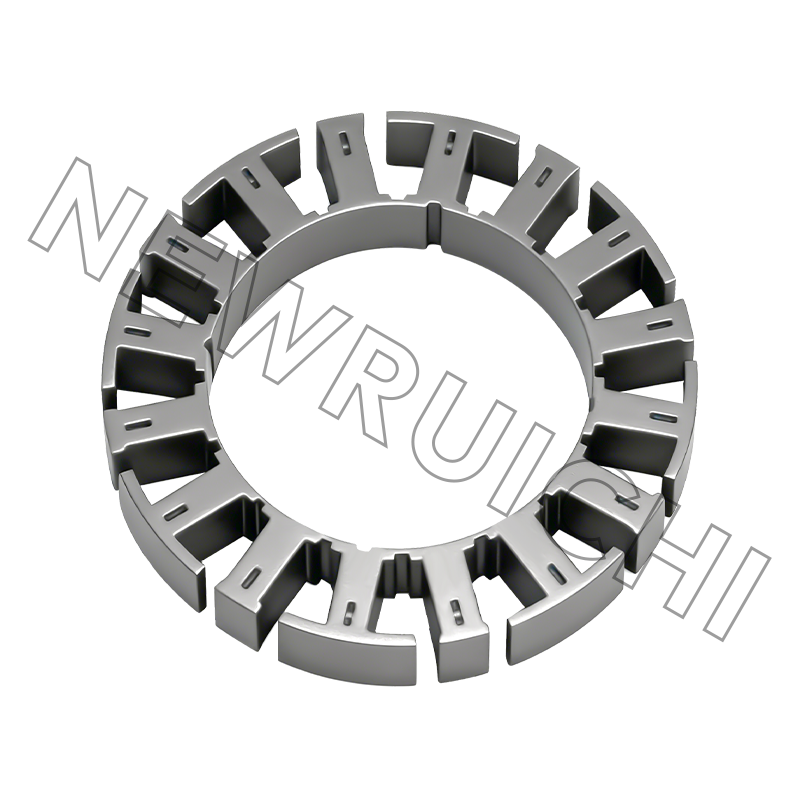
Permanent magnet synchronous motors (PMSMs) operate at synchronous speed and use rare-earth or ferrite magnets embedded in or mounted on the rotor to generate the rotor field, eliminating rotor copper losses and achieving higher efficiency density than induction motors at equivalent power ratings. PMSMs are the dominant motor type in new energy vehicles, high-performance servo drives, and direct-drive wind turbine generators. Their motor stator cores must be manufactured with exceptional slot geometry accuracy to ensure consistent air gap flux distribution and minimize cogging torque, which would otherwise manifest as vibration and noise in precision motion control applications.
Switched Reluctance and Synchronous Reluctance Motors
Switched reluctance motors and synchronous reluctance motors rely entirely on the variation of magnetic reluctance within the rotor core to generate torque, without permanent magnets or rotor windings. These types of motors place high demands on the motor core's permeability characteristics and saturation behavior because the torque production mechanism depends directly on the nonlinear magnetic properties of the core material. Cores for these motors are frequently produced from higher-silicon-content grades of electrical steel to maximize permeability at operating flux densities.
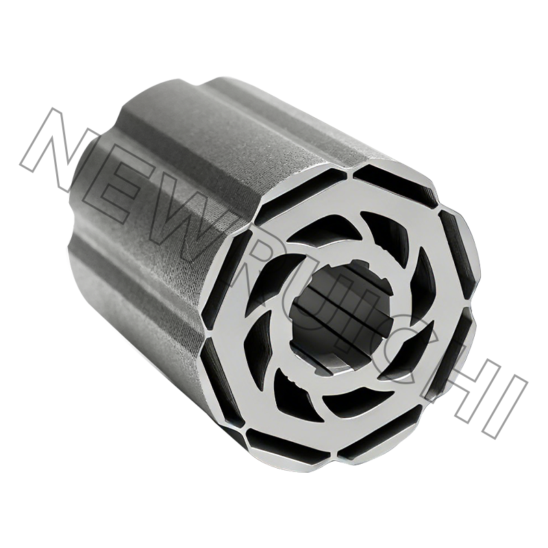
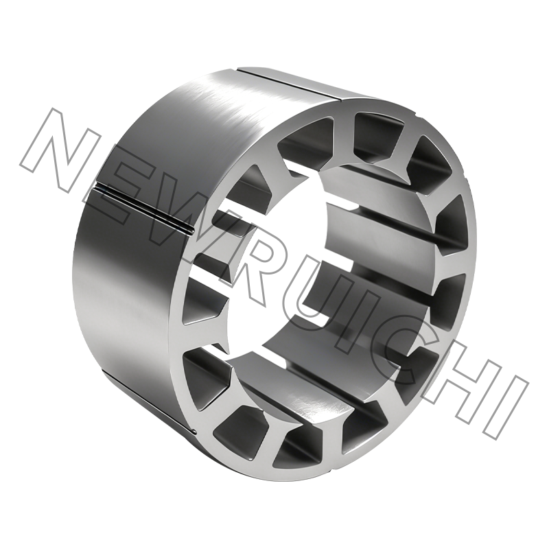
Motor Stator Core: Structure, Function, and Manufacturing
The motor stator core is the stationary magnetic structure that surrounds the rotor and houses the stator windings. It performs two simultaneous functions: providing a low-reluctance path for the rotating magnetic flux generated by the winding currents, and serving as the mechanical housing that positions and supports the winding conductors within the defined slot geometry. The precision with which the motor stator core is manufactured directly affects winding fill factor, slot insulation integrity, thermal conductivity to the motor frame, and the uniformity of the air gap between stator and rotor — all of which are critical performance parameters.
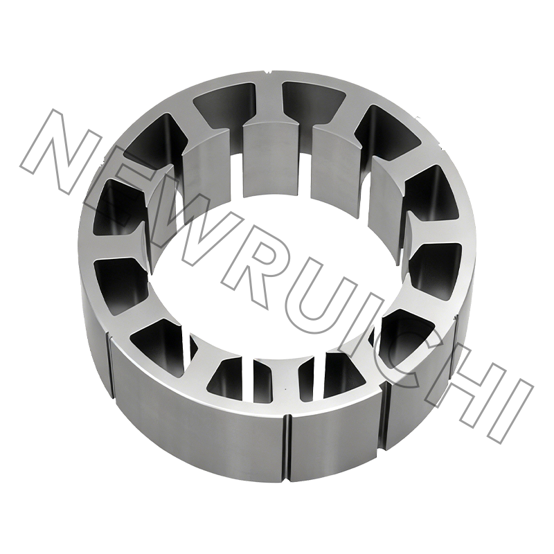
Structurally, the motor stator core consists of a yoke — the outer annular region that closes the magnetic circuit — and teeth that project radially inward to define the slots in which the windings are placed. The relationship between tooth width, slot opening width, and air gap length determines the flux density distribution in the stator and the magnitude of tooth saturation under full-load conditions. Advanced stamping technologies allow tooth and slot geometries to be produced with burr heights below 0.05 mm and dimensional tolerances within ±0.01 mm, ensuring that lamination-to-lamination stacking produces a core with smooth bore surface and accurate slot dimensions across the full stack height.
The stacking process itself — whether achieved through interlocking tabs, laser welding, adhesive bonding, or cleating — affects the mechanical rigidity of the finished motor stator core and the degree of interlaminar contact stress, which influences both the effective stacking factor and the vibration behavior of the assembled motor. Stacking factors above 97% are achievable with precision-produced laminations and controlled stacking pressure, maximizing the active magnetic cross-section available for flux conduction.
Silicon Steel Lamination Grades and Their Performance Impact
The selection of silicon steel lamination grade is the single most impactful material decision in motor core design. Electrical steel is classified by its core loss at standardized flux density and frequency conditions, with lower loss numbers indicating higher grade and higher cost. The following table summarizes common grades and their typical application areas:
| Grade (IEC) | Thickness (mm) | Core Loss W/kg at 1.5T/50Hz | Typical Application |
| M800-65A | 0.65 | ≤8.00 | General industrial motors, pumps |
| M470-50A | 0.50 | ≤4.70 | IE3 induction motors, rail transit |
| M330-35A | 0.35 | ≤3.30 | High-efficiency servo, wind power |
| M235-35A | 0.35 | ≤2.35 | New energy vehicles, premium PMSM |
| 20JNEH1200 | 0.20 | ≤1.20 | High-frequency traction, EV drive motors |
Selecting a lower-loss grade increases material cost but reduces motor operating losses over the product's entire service life, making total cost of ownership — rather than initial component cost — the appropriate evaluation metric for high-duty-cycle applications in mining, metallurgy, petrochemical, and nuclear power installations.
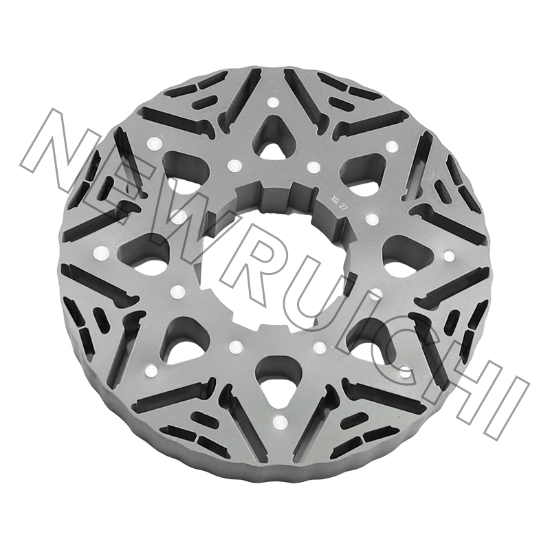
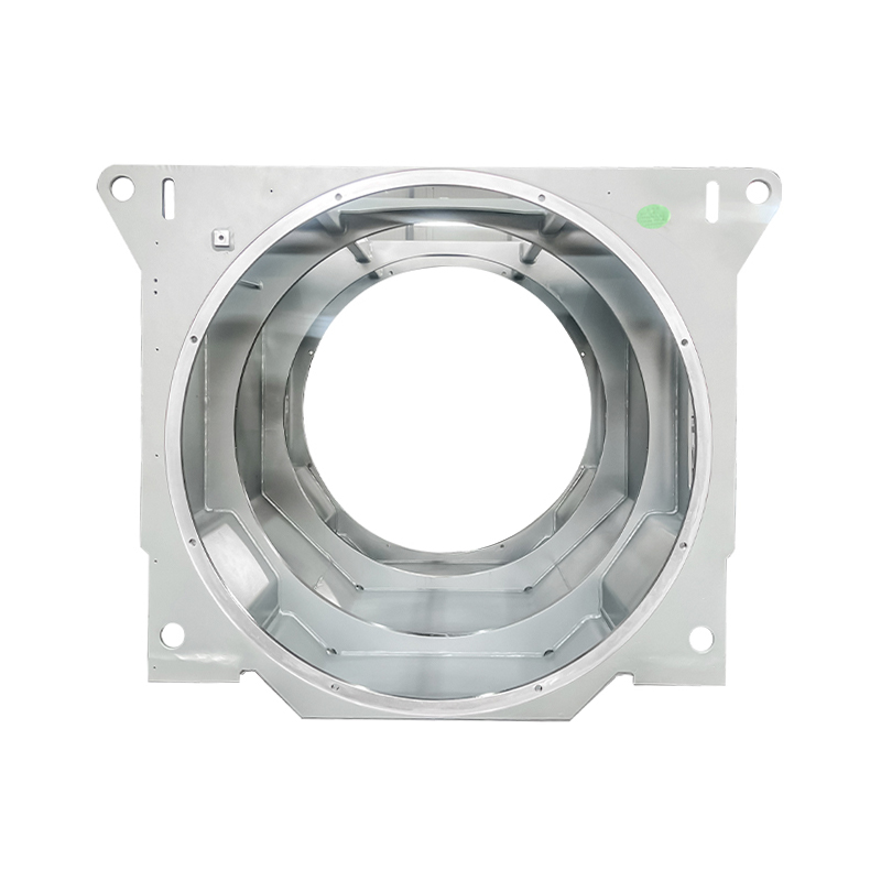
Industry Applications Spanning Energy and Heavy Industry
The breadth of industries that depend on high-quality motor cores reflects the universal importance of efficient electromagnetic energy conversion in modern infrastructure. Each application domain imposes specific requirements on core material, geometry, and manufacturing process.
- Nuclear and wind power: Generator stator cores in wind turbines and nuclear plant auxiliary systems must operate reliably for decades with minimal maintenance access. Low-loss laminations and precision stacking minimize thermal stress accumulation, extending insulation life and reducing unplanned downtime.
- Marine equipment: Shipboard motors face salt-air corrosion, vibration, and variable load profiles. Motor stator cores for marine drives use corrosion-resistant lamination coatings and robust mechanical stacking designs to maintain performance in harsh offshore environments.
- Mining and metallurgy: High-power drive motors for mills, crushers, hoists, and conveyors operate under heavy cyclic loads and elevated ambient temperatures. Cores produced from premium silicon steel grades with high saturation flux density support stronger power output without requiring oversized motor frames.
- Rail transit: Traction motors for metro, high-speed rail, and light rail vehicles require motor cores that maintain consistent electromagnetic characteristics across a wide speed and torque range while withstanding the mechanical shock and vibration of rail operation.
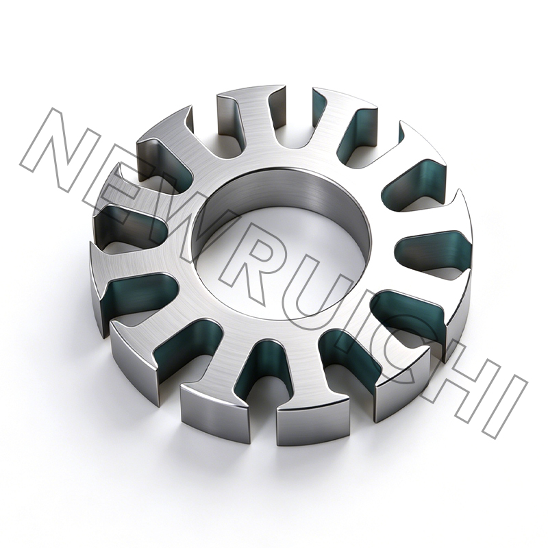
- New energy vehicles: EV and hybrid drive motors demand ultra-thin, low-loss laminations to maximize range per charge. High-slot-fill motor stator cores combined with hairpin winding technology are advancing peak efficiency beyond 97% in leading production drive units.
- Household appliances: Variable-speed compressor motors, direct-drive washing machine motors, and fan motors in air conditioners all use compact, efficiently designed motor cores that balance cost, noise, and energy performance for consumer market requirements.
Evaluating Motor Core Quality: Key Parameters to Specify
When sourcing motor cores or silicon steel laminations for motor manufacturing programs, engineers and procurement teams should define and verify a comprehensive set of quality parameters that go beyond basic dimensional conformance. Specifying these parameters in procurement documents and incoming inspection protocols ensures that the cores delivered to the production line will perform as designed throughout the motor's service life.
- Core loss (W/kg): Measured at specified flux density and frequency per IEC 60404 or equivalent standard; must align with the motor efficiency target.
- Stacking factor: The ratio of actual magnetic cross-section to geometric cross-section; values below specification indicate excessive burr height or surface coating thickness.
- Slot and bore dimensional tolerance: Critical for air gap consistency and winding insertion quality; typically specified at ±0.02 mm or tighter for precision servo applications.
- Interlaminar insulation resistance: Confirms that the surface coating adequately suppresses eddy current paths between laminations under the applied stacking pressure.
- Stack height tolerance: Ensures that the assembled motor stator core fits within the motor frame bore and positions the winding end-turns within the allowed axial envelope.
Partnering with a motor core supplier that applies advanced stamping and stacking technologies across the full production process — from raw silicon steel coil to finished stacked core — provides the traceability and process consistency needed to support both high-volume appliance production and low-volume, high-specification industrial and energy sector programs. The ability to supply a complete range of high-efficiency and low-loss motor cores and laminations from a single source simplifies supply chain management, reduces qualification overhead, and ensures that electromagnetic and mechanical performance specifications are maintained with the consistency that modern motor manufacturing demands.
Your email address will not be published. Required fields are marked *


![]() Email: [email protected]
Email: [email protected]
[email protected]
[email protected]
![]() Telephone/Phone:
+86-18861576796 +86-18261588866
Telephone/Phone:
+86-18861576796 +86-18261588866
+86-15061854509 +86-15305731515
Copyright © Wuxi New Ruichi Technology Co., Ltd. / Wuxi Cailiang Machinery Co., Ltd. All rights reserved.
Stator And Rotor Cores Manufacturers
