 en
en
 русский
 Deutsch
How Does a Three-Phase Motor Work? Working Principle, Parts, and Efficiency
Open a standard three-phase induction motor and one detail stands out: no capacitor, no brush gear, no auxiliary starting winding. Connect the three supply leads and the rotor accelerates on its own. That self-starting behavior follows directly from the geometry and timing of three-phase power.
In short, a three-phase motor works by using three alternating currents offset by 120 electrical degrees to create a rotating magnetic field in the stator. That field induces current in the rotor cage, and the interaction between the rotor field and the stator field produces torque. With no direct electrical contact to the rotor, the design stays simple, rugged, and efficient.
Core conclusion
Torque in a three-phase induction motor comes from a continuously rotating magnetic field and the slip that sustains rotor induction. The rotor always runs slower than the field under load; that small speed difference is what keeps the motor producing torque.
Content
- 1 Three-Phase Power: What the Name Really Means
- 2 The Working Principle in Five Steps
- 3 Stator and Rotor Construction That Makes It Possible
- 4 Three-Phase vs Single-Phase Induction Motors
- 5 Hidden Metrics: Efficiency, Slip, and Power Factor
- 6 Where Three-Phase Motors Dominate
- 7 Specifying and Sourcing a Three-Phase Motor
- 8 Maintenance and Compliance Practices That Protect Service Life
Three-Phase Power: What the Name Really Means
A three-phase supply is three sinusoidal voltages of equal frequency and amplitude, shifted by 120 electrical degrees. In a common 230/400 V system, each phase-to-neutral voltage is 230 V and the voltage between any two phases is 400 V. Because the waveforms peak at different instants, the combined magnetic pull on the stator never collapses to zero; it moves continuously around the air gap.
That continuous motion changes everything compared with a single-phase machine.
Constant torque delivery
Power arrives in overlapping peaks, so torque ripple is small. Complex loads run smoother with less vibration and noise.
Self-starting field
The rotating field exists as soon as the phases are energized, so no capacitor or centrifugal switch is needed. Swapping any two supply leads reverses rotation.
Higher power density
For the same frame size and cooling, a three-phase motor delivers more shaft power than a single-phase unit, so the machine can be smaller and lighter.
The Working Principle in Five Steps
The working sequence follows Faraday's law and Lenz's law in a repeating loop:
- Energize the stator windings. Distributed windings in stator slots energize in sequence because each phase peaks 120° after the previous one. The result is a rotating magnetic field moving around the stator bore at synchronous speed, ns = 120f/P, where f is frequency in hertz and P is the number of poles.
- Induce voltage in the rotor. At standstill, the rotor conductors see changing magnetic flux, so voltage is induced exactly as Faraday's law predicts.
- Circulate rotor current. The rotor cage is a closed conductor loop, so induced voltage drives current through the rotor bars. That current creates a field opposing the change that produced it.
- Generate torque. The rotor field is dragged by the stator field, so the rotor chases the rotating field and starts turning.
- Settle below synchronous speed. If the rotor caught the field, induction would stop and torque would vanish. The difference is slip, s = (ns - nr)/ns, typically 0.5-3% at full load.
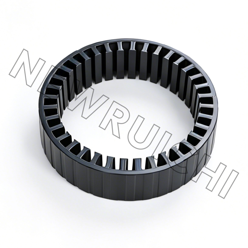
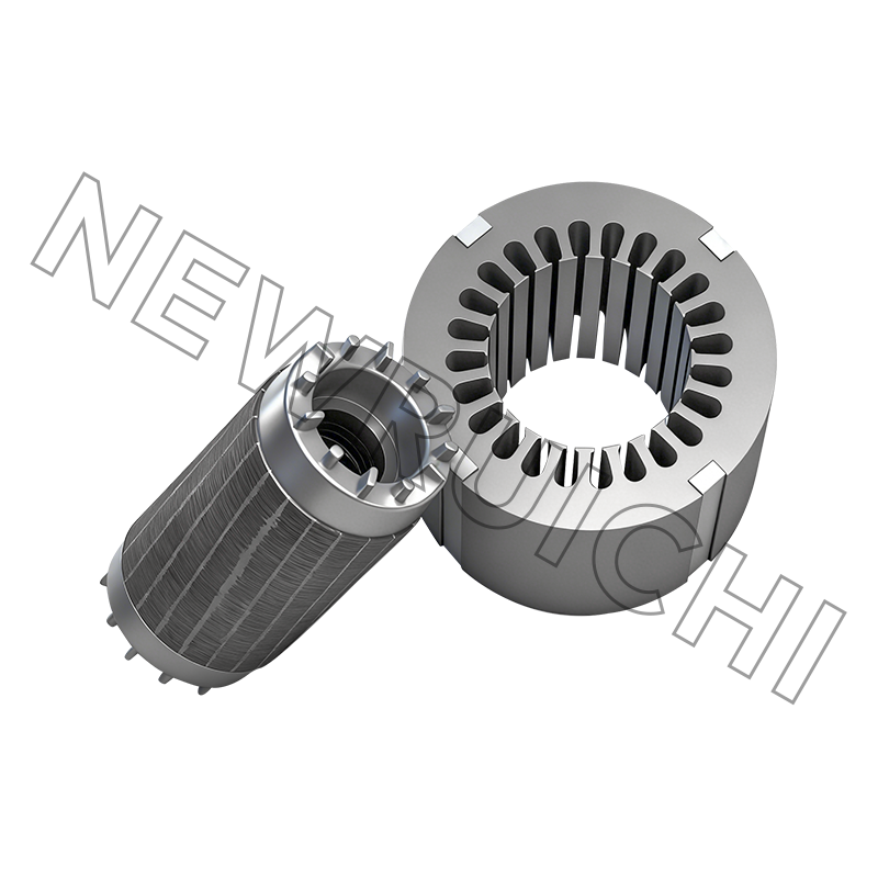
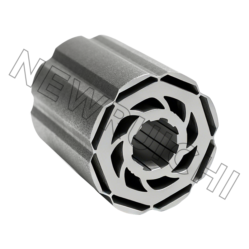
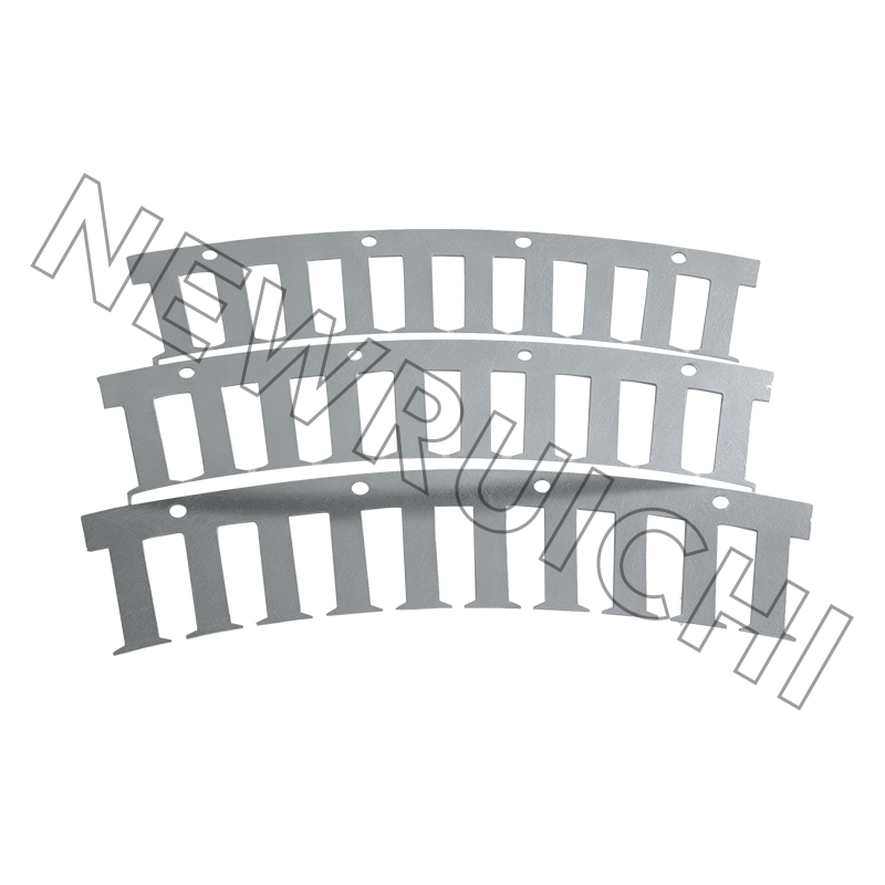 AC Motor Stator and Rotor Core Assembly with Laminated Silicon SteelExplore the stator and rotor core assembly that stacks non-oriented silicon steel laminations to reduce eddy-current and hysteresis losses, supporting smooth, efficient motor operation in industrial and HVAC applications.View Product →
Stator and Rotor Construction That Makes It Possible
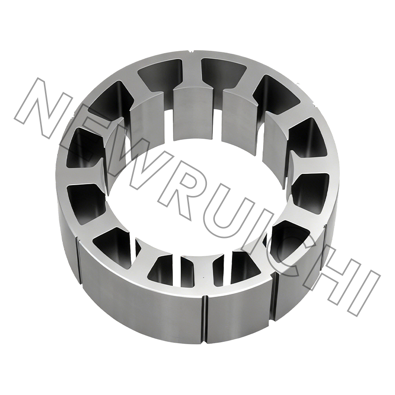
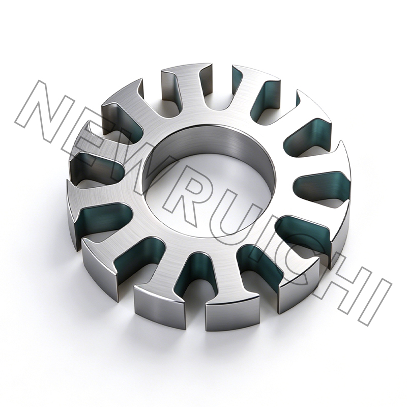
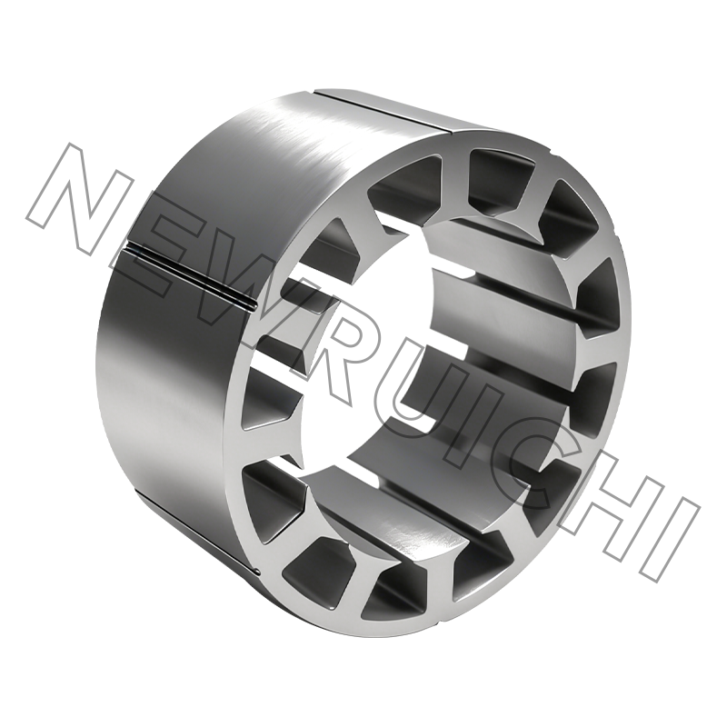
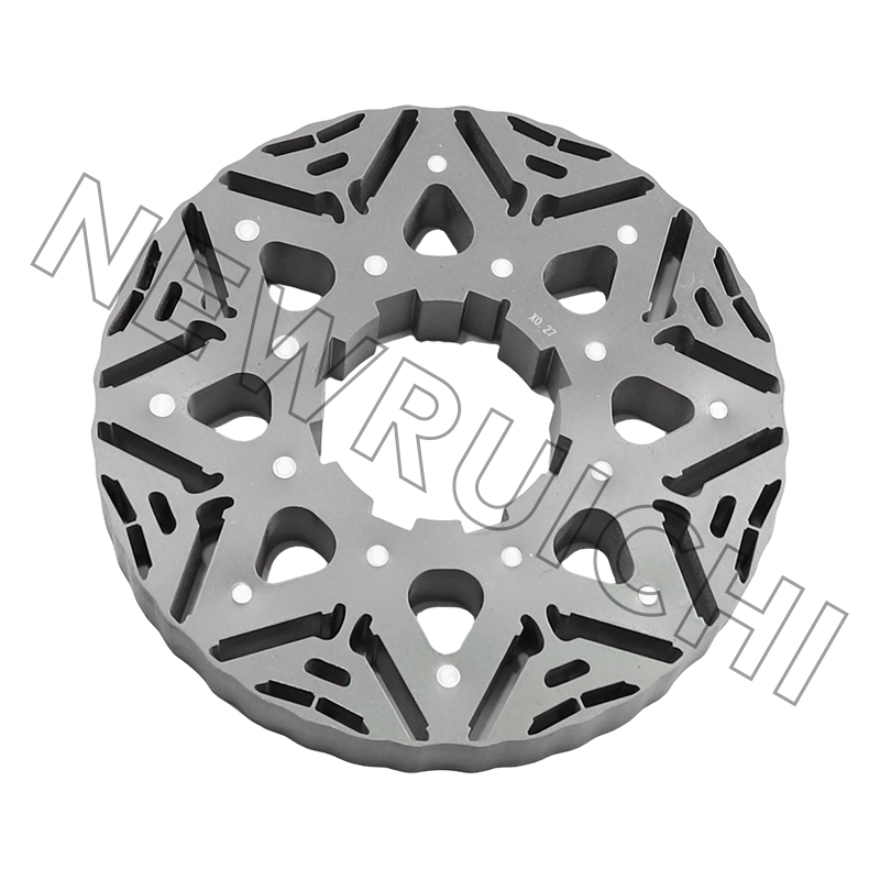
The stator core is a stack of thin silicon-steel laminations, punched with slots and held together by interlocking, bonding, or welding. Laminations limit eddy-current losses, and the silicon content raises resistivity and lowers hysteresis loss. Copper or aluminum coils sit in the slots, connected phase by phase. To explore the roles of each part in more detail, see how a stator and rotor work in an electric motor.
The rotor turns inside the stator across a narrow air gap, typically 0.3-1.5 mm. A squirrel-cage rotor uses aluminum or copper bars short-circuited by end rings; a wound rotor uses insulated windings brought out to slip rings for higher starting torque and speed control.
Performance lives in details: the steel grade, punching burr, stacking method, and air-gap evenness determine core loss, noise, and vibration. A cleanly made core is what lets a motor meet its efficiency label instead of running hot from day one.
Three-Phase vs Single-Phase Induction Motors
The differences go beyond the number of supply wires. The table below summarizes what they mean for a buyer or design engineer.
| Parameter | Single-phase | Three-phase |
|---|---|---|
| Supply | One phase plus neutral | Three phases, 120° apart |
| Starting | Requires capacitor or auxiliary winding | Self-starting |
| Starting torque | Low to moderate | High and controlled |
| Efficiency | Moderate | Higher; IE2-IE4 typical |
| Torque smoothness | Noticeable pulsation | Nearly constant |
| Typical range | Usually below 2-3 kW | From about 0.4 kW to several MW |
| Typical use | Fans, small pumps, domestic tools | Industrial pumps, compressors, conveyors, machine tools |
Once a three-phase supply is available, the comparison is rarely close. Three-phase motors win on efficiency, torque smoothness, and cost per kilowatt; single-phase remains only where supply infrastructure forces it.
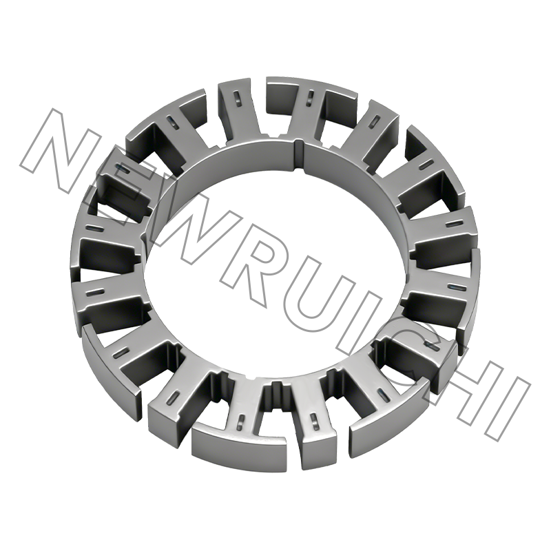
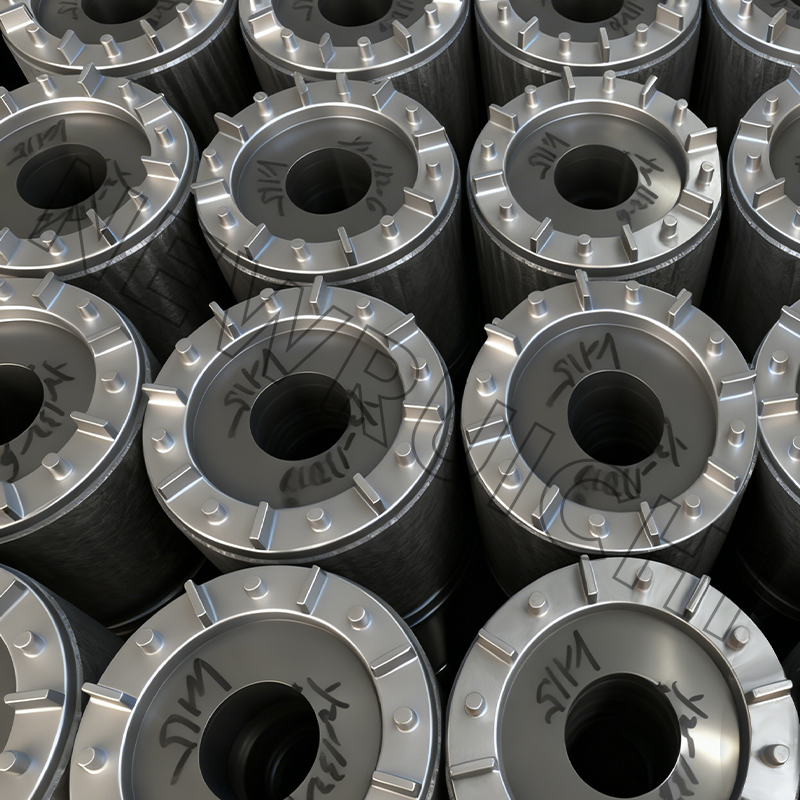 Interlock Laminated Core for High-Performance Motors and TransformersThis weld-free, glue-free interlock laminated core provides tightly aligned laminations for uniform magnetic paths, enabling mass production with dimensional consistency and stable performance in motors and transformers.View Product →
Hidden Metrics: Efficiency, Slip, and Power Factor
Rated power states what the motor can do, not what it costs to run. Efficiency, slip, and power factor govern operating cost, temperature rise, and starting behavior.
Efficiency vs load for a typical IE3 three-phase induction motor
25% load
50% load
75% load
100% load
125% load
Slip tells the same story: an oversized motor runs farther from its rated slip and efficiency drops, while rotor temperature rises. Normal full-load slip is 0.5-3%; power factor commonly lands between 0.7 and 0.9, and a low power factor draws excess line current.
Much of this behavior is fixed in the core. Because the stator and rotor laminations decide magnetic losses, many motor makers now buy ready-to-install finished cores from specialized suppliers instead of running their own stacking lines.
Where Three-Phase Motors Dominate
Three-phase induction motors consume most of the electrical energy used in industry. Their application mix clusters around sectors where reliability and efficiency pay off.
- Pumps and compressors - 35%
- Fans and blowers - 20%
- Conveyors and material handling - 15%
- Machine tools and industrial machinery - 15%
- HVAC, marine, electric vehicles, and other - 15%
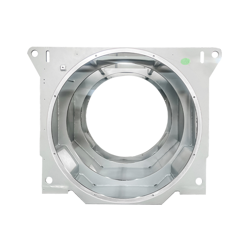
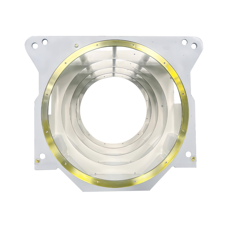
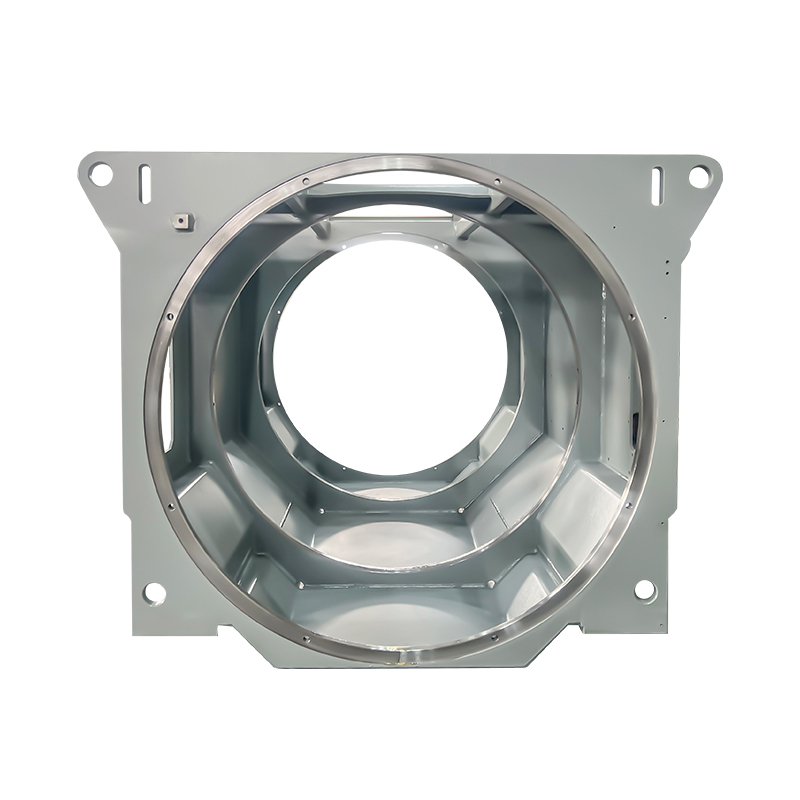
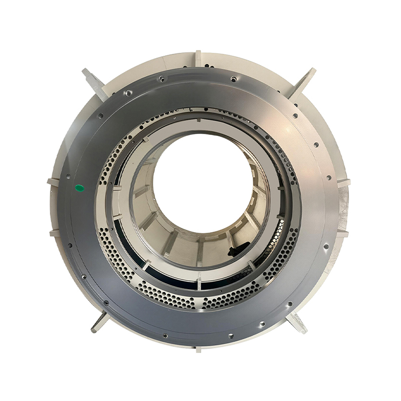
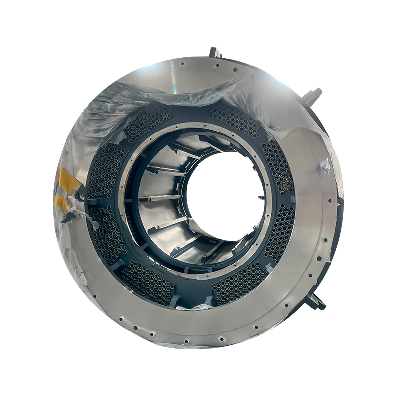
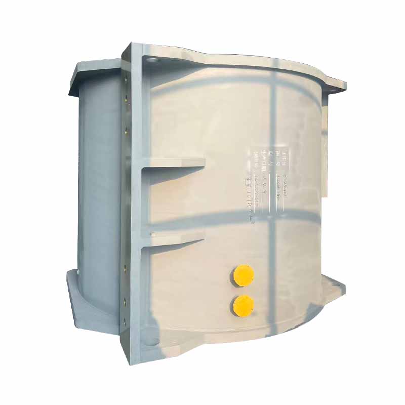
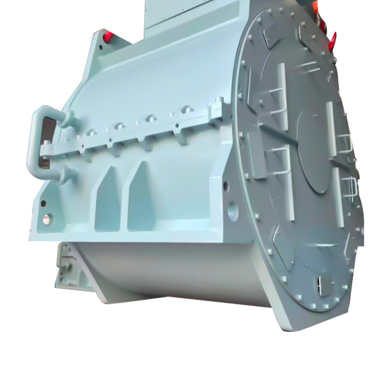
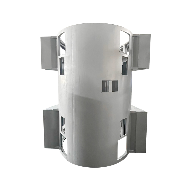
Each sector shapes the hardware around the motor. Wind turbine generators need welded box-type frames that handle bending and axial loads; marine motors use water-cooled, corrosion-treated housings; high-voltage motors rely on aluminum-tube or vertical cooling designs. The electrical principle stays the same, but mechanical integration changes completely.
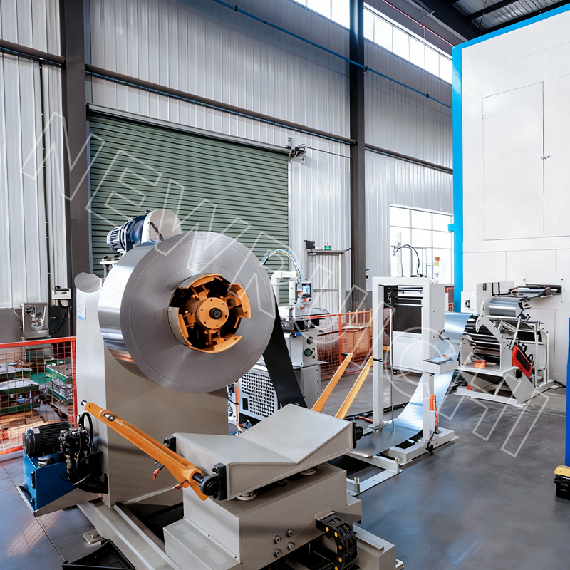 High Grade Non-Grain-Oriented Silicon Steel Coils for Efficient MotorsManufactured NGO silicon steel delivers low core loss and excellent magnetic properties, available in various widths and diameters for continuous stamping, improving motor efficiency and reducing operational costs.View Product →
Specifying and Sourcing a Three-Phase Motor
For an OEM, specifying a motor means defining the load, efficiency, supply, and supply chain together. A practical sequence looks like this:
1. Define the load
Constant torque, variable torque, or constant power? Duty cycles such as S1 or S5 determine thermal rating and frame size.
2. Set efficiency and protection targets
IEC 60034-30-1 defines IE2, IE3, and IE4 classes; insulation class F or H and an IP rating come next.
3. Match the supply
Confirm voltage and frequency (400 V/50 Hz or 460 V/60 Hz) and choose direct-on-line, star-delta, or VFD starting.
4. Choose core and cooling architecture
Frame material, cooling method (IC411, IC416, water-cooled), shaft configuration, and silicon steel grade of the laminations all affect performance.
5. Qualify the supplier
Check ISO 9001 quality systems, IATF 16949 for automotive programs, material certificates, and evidence of the manufacturing capabilities used to produce the core.
6. Validate with a sample
Run a heat-run test, measure efficiency and vibration, inspect dimensions, then approve serial production.
For motor builders, sourcing the stator and rotor core from a partner with tight dimensional control, documented material grades, and fast sample turnaround shortens the development cycle. Supplier qualification is where the electrical design meets manufacturing reality.
Maintenance and Compliance Practices That Protect Service Life
A three-phase motor is mechanically simple, but service life depends on conditions that are easy to overlook. Voltage imbalance leads the list: a 3% phase-to-phase imbalance can raise winding temperature by 25-40%, according to NEMA MG1. A 5% imbalance makes it worse and frequently causes insulation failure.
Routine checks keep the motor healthy:
- Measure phase-to-phase voltage under load after any supply-side change.
- Check insulation resistance between phases and to ground; record readings so trends become visible.
- Tighten terminal box connections; a loose connection can single-phase the motor and overheat the rotor.
- Monitor vibration for bearing wear and unbalance; set thresholds from the mounting type and speed.
- Follow the lubrication interval; over-greasing is as damaging as under-greasing.
Compliance is tightening. Efficiency rules based on IEC 60034-30-1 now require minimum IE classes for new motors in most industrial markets. For OEM projects, the steel grade certificate, lamination process parameters, and test reports become part of the compliance file. A supplier running ISO 9001 and IATF 16949 systems provides the traceability that export and automotive programs demand.
The three-phase motor rewards engineers who respect its physics. The rotating field sets the tempo, slip sustains induction, and the laminated core decides how much energy reaches the shaft. Specify the load honestly, choose the efficiency class deliberately, and verify the supplier's quality controls - the result is a drive system that runs for decades with predictable maintenance.
Your email address will not be published. Required fields are marked *


 Email: [email protected]
[email protected]
 Telephone/Phone:
+86-18861576796 +86-18261588866
Telephone/Phone:
+86-18861576796 +86-18261588866
+86-15305731515 +86-18861576796
Copyright © Wuxi New Ruichi Technology Co., Ltd. / Wuxi Cailiang Machinery Co., Ltd. All rights reserved.
Stator And Rotor Cores Manufacturers
