 en
en
 русский
 Deutsch
How Does a Stator and Rotor Work in an Electric Motor?
A stator and rotor work together through electromagnetic induction to convert electrical energy into mechanical rotation. The stator, the stationary outer component, receives alternating current to generate a rotating magnetic field. This field cuts across the rotor, the inner rotating component, inducing current flow within its conductors. The interaction between the stator's rotating magnetic field and the magnetic field created by the induced rotor current produces torque—the twisting force that spins the motor shaft. This fundamental principle governs every electric motor, from the compact units in household appliances to the massive drives powering wind turbines, mining conveyor systems, and nuclear reactor coolant pumps. The efficiency with which this energy conversion occurs depends heavily on the quality of the motor core: the stack of silicon steel laminations that channels magnetic flux through both stator and rotor with minimal energy loss.
Content
- 1 The Stator: Creating the Rotating Magnetic Field
- 2 The Rotor: Translating Magnetic Fields into Mechanical Torque
- 3 Stator and Rotor Interaction in Different Motor Types
- 4 Energy Loss Mechanisms in Stator and Rotor Cores
- 5 Manufacturing Precision: How Stamping and Stacking Affect Performance
- 6 Applications Where Stator and Rotor Quality Are Critical
- 7 The Air Gap: Small Distance, Large Consequences
The Stator: Creating the Rotating Magnetic Field
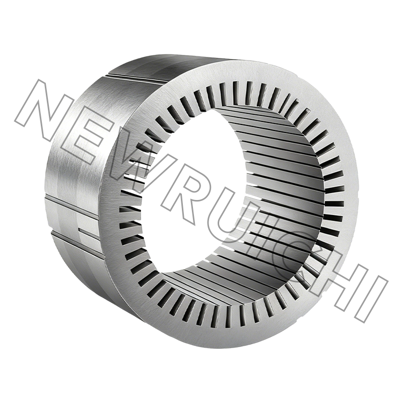
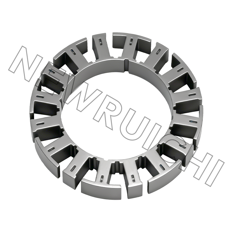
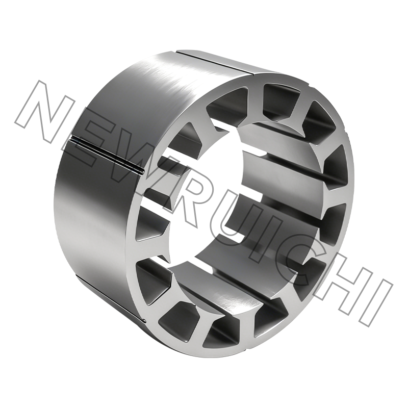
The stator forms the fixed outer shell of the motor and performs one primary function: generating a magnetic field that rotates in space. This rotation is achieved through the physical arrangement of copper windings inserted into slots cut into the stator core, a cylindrical stack of silicon steel laminations. When three-phase alternating current flows through these windings—each phase displaced by 120 electrical degrees from the others—the combined magnetic effect produces a field of constant magnitude that sweeps smoothly around the stator's inner circumference. The speed of this rotation, called the synchronous speed, is determined by the supply frequency and the number of magnetic poles in the winding design. A four-pole motor fed with 50 Hz current produces a field rotating at 1,500 rpm; the same motor at 60 Hz rotates at 1,800 rpm. This precise relationship between frequency, pole count, and speed allows motor designers to tailor output characteristics to specific industrial applications.
The Role of the Stator Core in Magnetic Efficiency
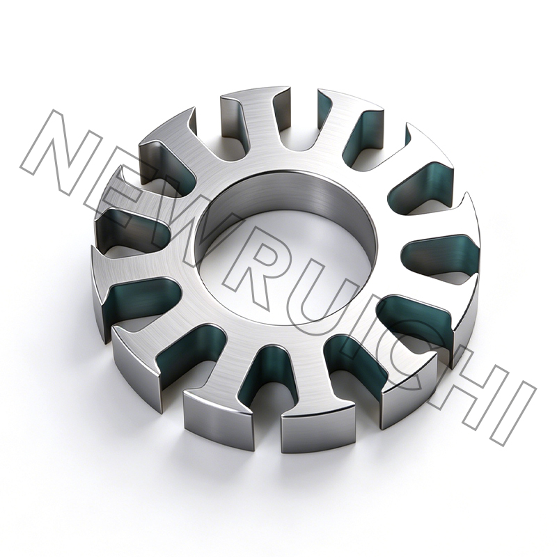
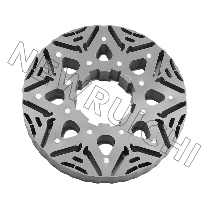
The stator core is not solid iron but a precisely stacked assembly of 0.35 mm or 0.50 mm thick silicon steel laminations, each electrically insulated from its neighbors by a thin oxide or varnish coating. This segmented construction addresses a fundamental problem in AC machines: the alternating magnetic flux induces circulating currents—eddy currents—within any solid conductive mass exposed to a changing magnetic field. These eddy currents dissipate energy as heat and reduce motor efficiency. By dividing the core into thin, insulated laminations, the path for eddy currents is restricted to the cross-section of each individual sheet, reducing eddy current losses by 85–95% compared to a solid steel core of the same dimensions. The silicon content of the steel, typically 2–3.5%, increases electrical resistivity further, suppressing eddy currents while also improving magnetic permeability—the material's ability to conduct magnetic flux. High-grade silicon steel laminations in premium motor cores achieve flux densities of 1.7–1.8 Tesla at moderate magnetizing currents, a combination that directly translates to higher torque per ampere of input current.
The Rotor: Translating Magnetic Fields into Mechanical Torque
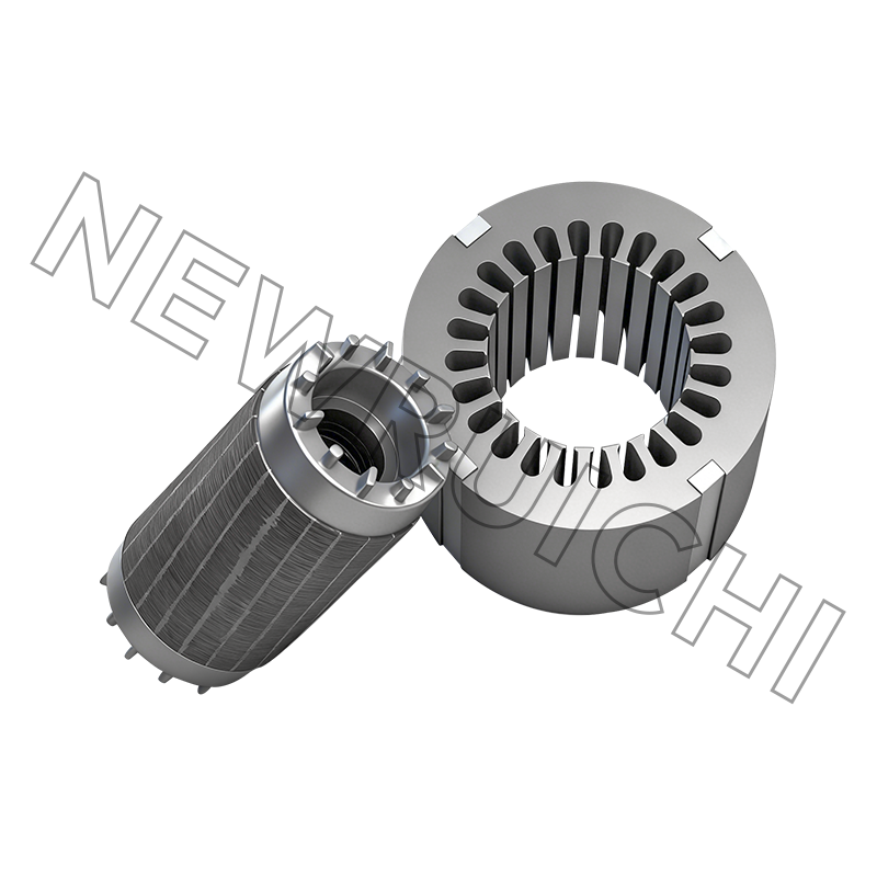
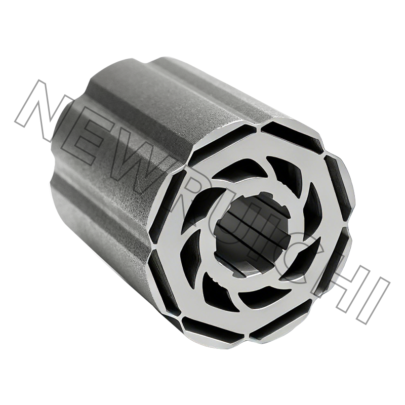
The rotor sits inside the stator, mounted on bearings that allow it to spin freely within the rotating magnetic field. Its construction varies by motor type, but the operating principle remains consistent: the rotor carries conductors that experience a force when exposed to the stator's magnetic field. In the most common industrial motor, the squirrel-cage induction motor, the rotor consists of a laminated iron core with evenly spaced slots containing aluminum or copper bars shorted together by end rings at both ends. This simple, robust structure has no external electrical connections, no brushes, and no windings that require insulation—reasons it dominates industrial drive applications. When the stator's rotating field sweeps past these stationary rotor bars, the relative motion between the field and the bars induces a voltage that drives current through the bars. The current-carrying bars within the magnetic field experience a Lorentz force perpendicular to both the current direction and the magnetic field lines, producing the torque that accelerates the rotor in the direction of the rotating field.
Slip: Why the Rotor Never Catches the Field
A fundamental characteristic of induction motors is that the rotor can never reach the exact speed of the stator's rotating magnetic field. The difference between synchronous speed and actual rotor speed, expressed as a percentage, is called slip. At full load, a typical four-pole motor operates with 2–5% slip, meaning a 1,500 rpm synchronous field drives the rotor at 1,425–1,470 rpm. This speed difference is necessary because electromagnetic induction requires relative motion between the magnetic field and the conductor. If the rotor caught up to the field, there would be no relative motion, no induced rotor current, and consequently no torque. The relationship between slip and torque defines a motor's performance curve: at zero speed during startup, slip is 100% and starting torque can exceed 200% of rated torque in high-efficiency designs. As the rotor accelerates, slip decreases and torque settles at its rated value once the motor reaches operating speed. This self-regulating behavior allows induction motors to adapt to changing mechanical loads without external control systems.
Stator and Rotor Interaction in Different Motor Types
While the stator-rotor magnetic interaction underpins all electric motors, the specific implementation varies across motor types to suit different application needs.
Induction Motors
The workhorse of industrial drive systems, induction motors use a squirrel-cage rotor that requires no permanent magnets, no slip rings, and no electrical connections to the rotating shaft. The stator's rotating field induces rotor currents through transformer action, with the air gap between stator and rotor acting as the magnetic coupling medium. This design provides exceptional reliability and suits the continuous-duty requirements of mining conveyor drives, petrochemical pumps, and marine propulsion systems where maintenance access is limited and downtime costs are high. The trade-off is that rotor current generation consumes magnetizing current that does not contribute to output power, slightly lowering efficiency compared to permanent magnet designs.
Permanent Magnet Synchronous Motors
In permanent magnet motors, the rotor carries high-strength neodymium or samarium-cobalt magnets that generate a fixed magnetic field without requiring induced current. The rotor locks into synchronism with the stator's rotating field, operating at exactly synchronous speed with zero slip. Eliminating the rotor current generation losses improves efficiency by 3–8 percentage points compared to equivalent induction motors, a margin that makes permanent magnet designs dominant in new energy vehicle traction drives and high-efficiency household appliances. The stator core in these motors faces particularly demanding magnetic conditions because the rotor's permanent magnets create a constant flux that saturates portions of the stator teeth even when the motor is stationary. The lamination steel must maintain high permeability under these DC-biased conditions to avoid additional hysteresis losses.
Energy Loss Mechanisms in Stator and Rotor Cores
The motor core, encompassing both stator and rotor laminations, is the site of two primary energy loss mechanisms that determine overall motor efficiency. Understanding these losses explains why lamination quality directly affects operating cost across a motor's 15–30 year service life.
| Loss Type | Physical Cause | Key Influencing Factor | Mitigation Strategy |
|---|---|---|---|
| Hysteresis Loss | Energy required to repeatedly reverse magnetic domains in the steel | Silicon content and grain size of the steel | Use high-silicon (2–3.5%) steel with optimized grain orientation |
| Eddy Current Loss | Circulating currents induced in the core material by changing flux | Lamination thickness and inter-laminar insulation quality | Use thinner laminations (0.35 mm) with durable insulation coating |
| Stray Load Loss | Flux leakage and harmonic fields at slot openings and air gap | Slot geometry and winding distribution | Optimize slot shape and use skewed rotor slots |
Hysteresis loss occurs because the magnetic domains within the silicon steel resist being flipped back and forth as the alternating magnetic field reverses direction. Each reversal consumes a small amount of energy that appears as heat in the core. This loss is proportional to the frequency of magnetic reversal and depends on the intrinsic magnetic properties of the steel. Silicon alloying reduces hysteresis loss by increasing the steel's electrical resistivity and by refining the grain structure so that domain walls move more freely. In practice, upgrading from standard-grade to high-grade silicon steel laminations reduces total core loss by 15–25% at 50 Hz operation, a margin that can shift a motor's efficiency classification from IE3 to IE4 without changing the copper winding design.
Manufacturing Precision: How Stamping and Stacking Affect Performance
The electromagnetic performance of a stator-rotor pair depends as much on manufacturing precision as on material selection. Each lamination is produced by stamping the slot pattern, bore diameter, and outer contour from silicon steel sheet using high-speed progressive dies. The dimensional tolerance on the stator bore and rotor outer diameter directly determines the air gap between the two components, which in a medium-sized industrial motor is typically 0.5–1.5 mm. A deviation of just 0.1 mm from the designed air gap width changes the magnetizing current requirement by 5–10%, affecting both efficiency and power factor. Advanced stamping processes maintain slot and bore tolerances within ±0.03 mm, ensuring that the air gap is uniform around the entire circumference. An uneven air gap creates unbalanced magnetic pull—a radial force that bends the shaft slightly and loads the bearings asymmetrically, increasing noise, vibration, and bearing wear rates.
After stamping, laminations are stacked and joined into a rigid core using interlocking, welding, or adhesive bonding techniques. The stacking process must maintain precise alignment of the slots so that the copper windings can be inserted without scraping their insulation. Modern automated stacking systems achieve lamination alignment within 0.05 mm cumulative error across a core length that may exceed 500 mm in large motors. The stacking factor—the proportion of the core length occupied by steel rather than insulation or air between laminations—typically exceeds 97% in high-quality cores, maximizing the magnetic cross-section for a given core volume. This manufacturing discipline, applied to both stator and rotor cores, ensures that the electromagnetic design intent translates faithfully into the assembled motor's performance.
Applications Where Stator and Rotor Quality Are Critical
The stator-rotor core assembly represents the single largest factor in a motor's long-term energy consumption. In applications where motors run continuously or near-continuously, the financial impact of core efficiency accumulates dramatically over the equipment lifetime.
- Nuclear power coolant pumps: Motors run for 18–24 months between refueling outages. A core efficiency improvement of 1% on a 5 MW pump motor saves approximately 438 MWh annually, equivalent to $40,000–$60,000 per year at industrial electricity rates.
- Wind turbine generators: The stator and rotor cores experience variable frequency operation as wind speed changes. Low-loss silicon steel maintains efficiency across the full speed range, critical for maximizing energy capture from gusty wind conditions.
- Mining conveyor drives: Motors operate under high starting torque and frequent load cycling. Lamination stacks that resist delamination under thermal cycling prevent the gradual increase in vibration that leads to winding insulation failure.
- New energy vehicle traction motors: The stator cores in automotive traction motors must deliver peak flux density for acceleration while maintaining low losses during highway cruising. Thin-gauge, high-silicon laminations achieve this dual requirement, contributing to the 95%+ peak efficiency of modern EV drive units.
- Rail transit traction motors: Frequent acceleration from station stops subjects rotor bars and core to cyclic thermal stress. Consistent lamination quality prevents the development of hot spots that degrade insulation and shorten motor life.
The Air Gap: Small Distance, Large Consequences
The space between the stator bore and the rotor outer surface—the air gap—is the region where electromagnetic energy transfer actually occurs. Despite being physically empty, this gap represents the most magnetically significant dimension in the entire motor. The magnetic flux generated by the stator windings must cross this gap to reach the rotor, and the reluctance (magnetic resistance) of the air gap is thousands of times higher than that of the silicon steel core. As a result, the air gap dimensions determine how much magnetizing current the motor draws to establish the working magnetic field. Reducing the air gap from 1.0 mm to 0.7 mm can lower magnetizing current by 25–30%, improving power factor and reducing stator copper losses. However, a narrower gap demands tighter manufacturing tolerances and better bearing precision to prevent rotor-stator contact under load or thermal expansion. The gap dimension represents an engineering compromise between electromagnetic performance and mechanical reliability, one that motor designers revisit for each application class.
Your email address will not be published. Required fields are marked *


 Email: [email protected]
[email protected]
 Telephone/Phone:
+86-18861576796 +86-18261588866
Telephone/Phone:
+86-18861576796 +86-18261588866
+86-15305731515 +86-18861576796
Copyright © Wuxi New Ruichi Technology Co., Ltd. / Wuxi Cailiang Machinery Co., Ltd. All rights reserved.
Stator And Rotor Cores Manufacturers
