 en
en
 русский
 Deutsch
Explosion-Proof Motors: Selection Guide, Hazardous Area Classifications, and Cooling
In a chemical processing plant, a vertical pump motor had been running for years. The plant used a hydrogen-rich atmosphere in one of the reactors. A routine restart produced an arc inside the terminal box. The motor's casting was old and had been re-machined many times, so the flameproof joint gaps were no longer within specification. The internal explosion did not stay inside. The flame escaped through the joint, igniting the surrounding gas. The damage was severe. This is the type of incident that explosion-proof motors are built to prevent.
Before we examine what makes a motor explosion-proof, the key point is this: an explosion-proof motor is not explosion-proof in the sense that it never explodes. It is designed to contain an internal explosion. The motor's enclosure must withstand the pressure of an internal blast, cool the hot exhaust gases, and prevent any flame, spark, or hot particle from reaching the outside explosive atmosphere. The reliability of that containment depends on precise mechanical engineering, correct material selection, and proper thermal management.
The most important decision factors for explosion-proof motors are the hazardous area classification, the temperature class, the enclosure joint design, and the cooling method. A motor that is properly classified, manufactured with tight flameproof gaps, and fitted with an appropriate cooling system can operate safely for many years. A motor that is simply "rated" or "certified" but mismatched to the actual gas group, dust type, or ambient temperature will lose its safety margin.
Content
- 1 How Explosion-Proof Motors Work: Core Principles
- 2 Data Comparison: Cooling Methods for Explosion-Proof Motors
- 3 Hidden Metrics: Surface Temperature and Thermal Load
- 4 Industry Applications and Market Distribution
- 5 Selection Guide: How to Choose an Explosion-Proof Motor
- 6 Maintenance, Inspection, and Compliance
How Explosion-Proof Motors Work: Core Principles
The principle behind a flameproof enclosure is simple but demanding. The motor frame, terminal box, and bearing housings form a sealed enclosure. If an internal arc occurs, the resulting pressure rise pushes hot gases through narrow gaps between machined surfaces. These gaps are not open paths; they are designed to allow gas to escape slowly while quenching the flame. The gap length and width are determined by the gas group and the enclosure's volume.
Enclosure strength
The casing must be able to withstand an internal explosion without deformation or rupture. Cast iron and steel are common, but the wall thickness and material grade must match the maximum explosion pressure.
Flameproof joints
Joints at the bearing caps, terminal box, and frame are machined to exact tolerances. The distance between mating surfaces, called the flamepath length, must be long enough to cool the flame below the ignition temperature of the surrounding atmosphere.
Temperature control
Even when the enclosure is strong enough, the external surface temperature must stay below the auto-ignition temperature of the hazardous gas or dust. This is why cooling fins, fan systems, and heat exchangers are essential.
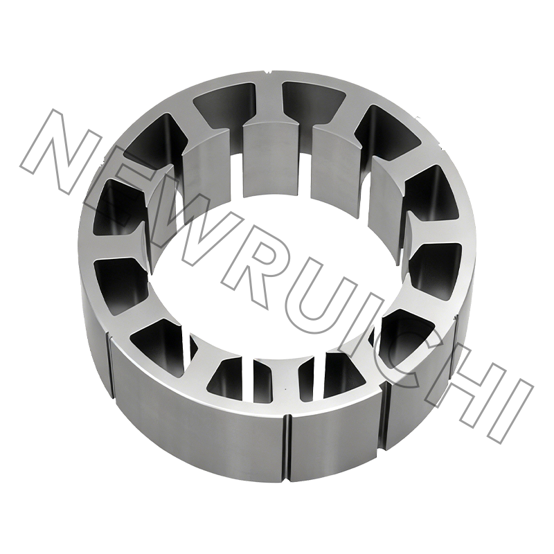
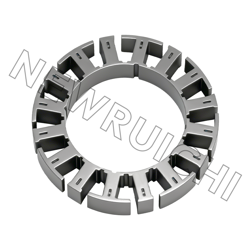
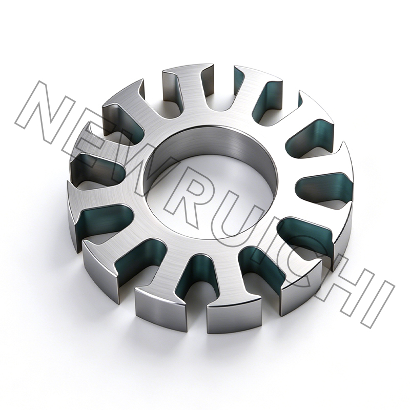
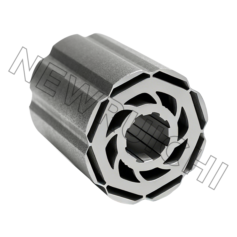
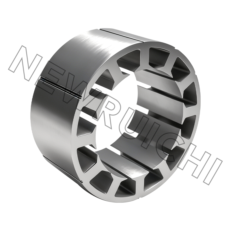
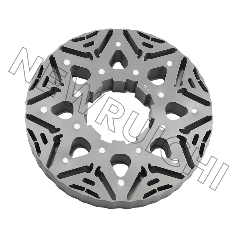
The motor core motor core laminations play a critical role in efficiency and thermal load. A high-quality stator and rotor core reduces iron losses, which lowers the overall heat generated inside the enclosure. Less heat means a smaller surface area is needed to keep the skin temperature within the temperature class limit.
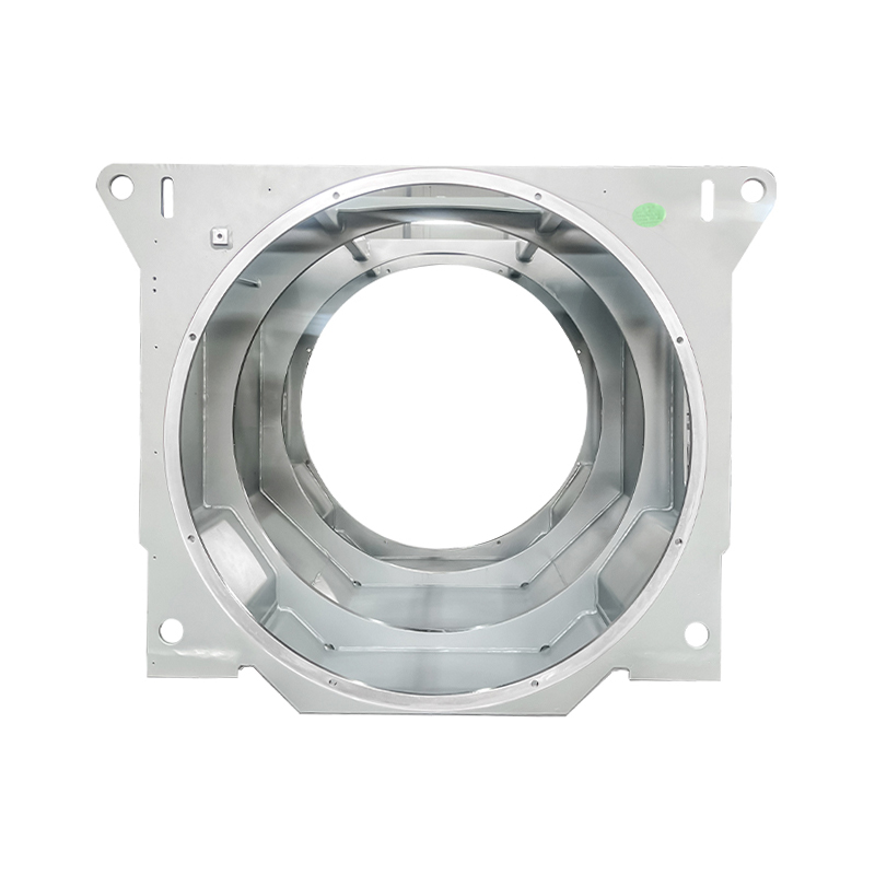
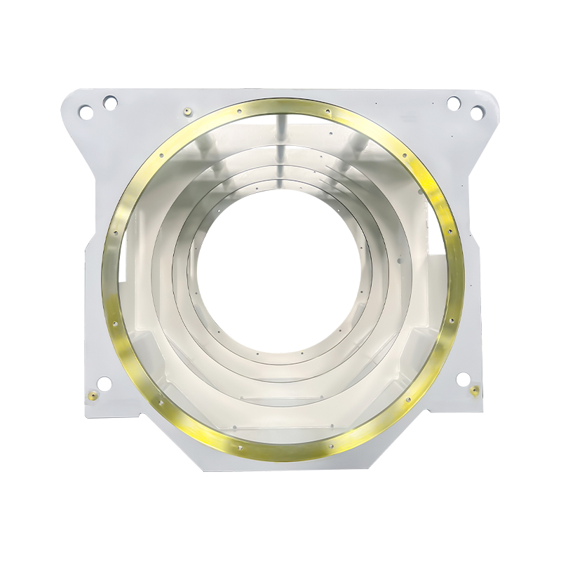
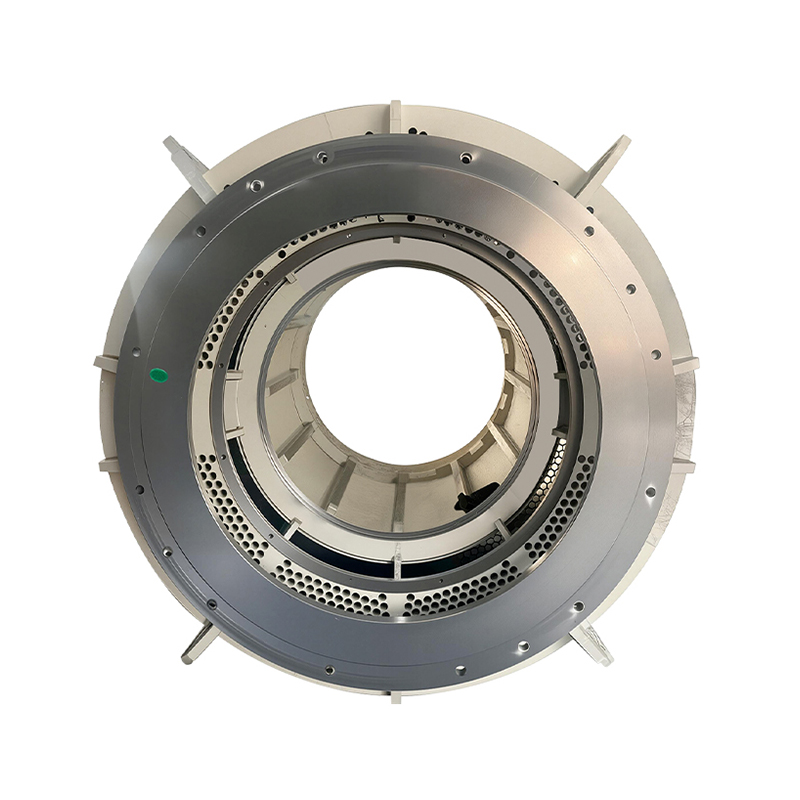
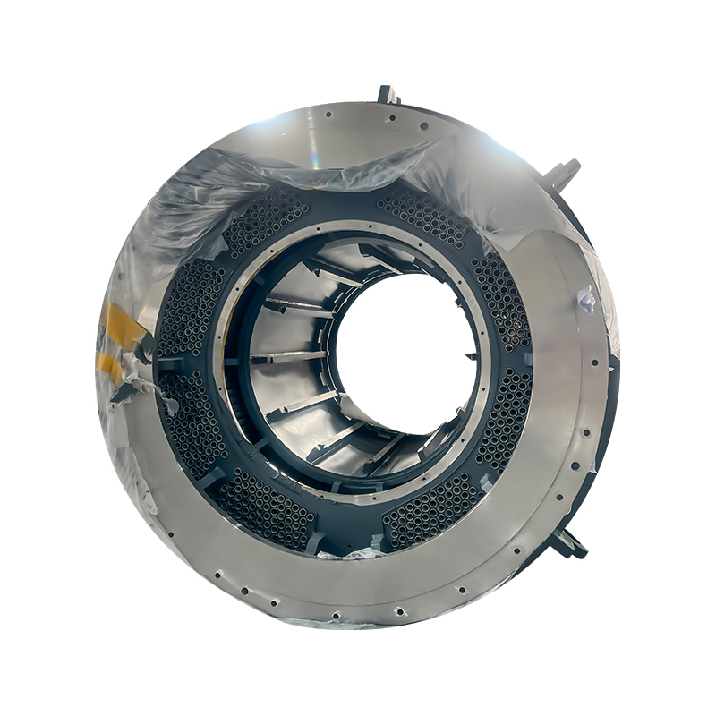
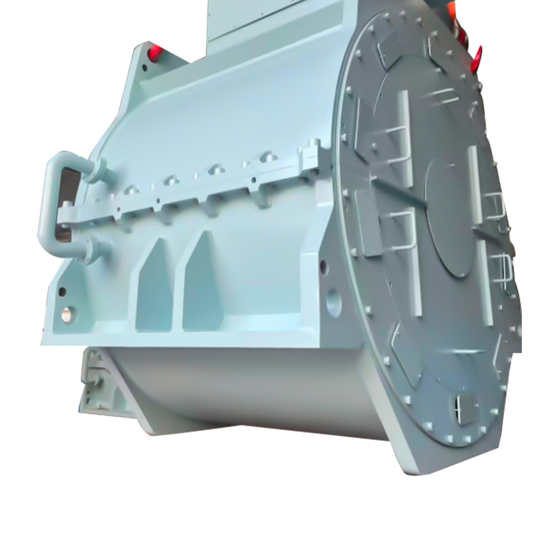
 Horizontal Aluminum Tube Cooling Machine Frame for Explosion-Proof MotorsThis integrated support and cooling frame uses aluminum pipes to circulate coolant, efficiently removing heat from the motor enclosure in hazardous locations. It helps maintain lower surface temperatures, supporting compliance with temperature class limits.View Product →
Data Comparison: Cooling Methods for Explosion-Proof Motors
In hazardous locations, the cooling method directly affects the maximum surface temperature and the attainable power rating. The following comparison shows typical performance differences between three approaches used in explosion-proof motors. Keep in mind that the actual numbers depend on frame size, ambient temperature, and the motor's duty cycle.
For hazardous area motors, when the temperature class is limited to T3 or T4, the cooling capacity often determines whether the motor can deliver the required torque. A water-cooled or externally-cooled frame may be selected instead of a sealed enclosure with natural convection. The frame material and cooling passage design must also be compatible with the explosive environment.
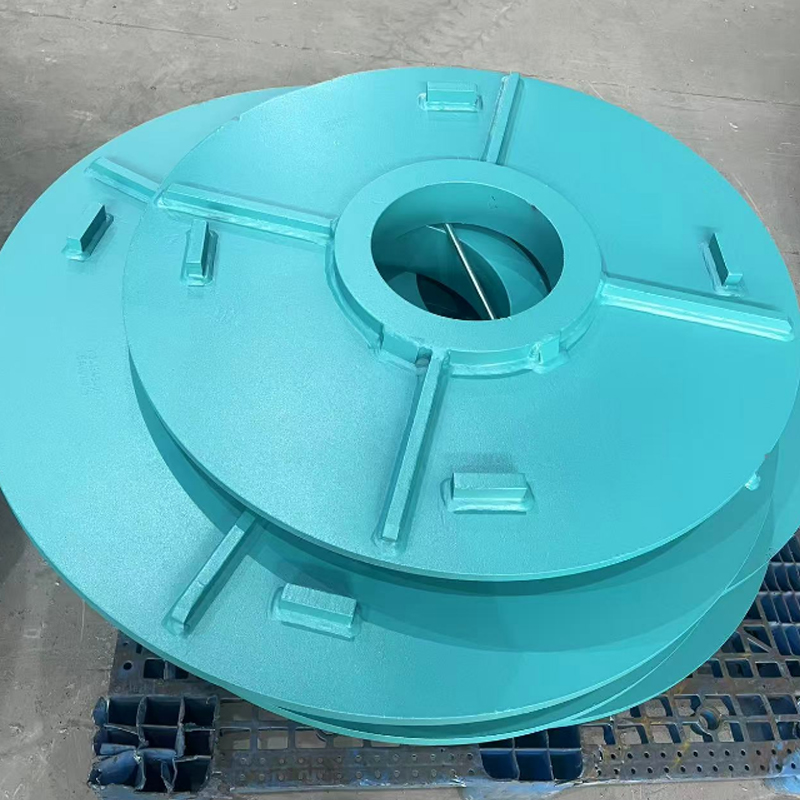
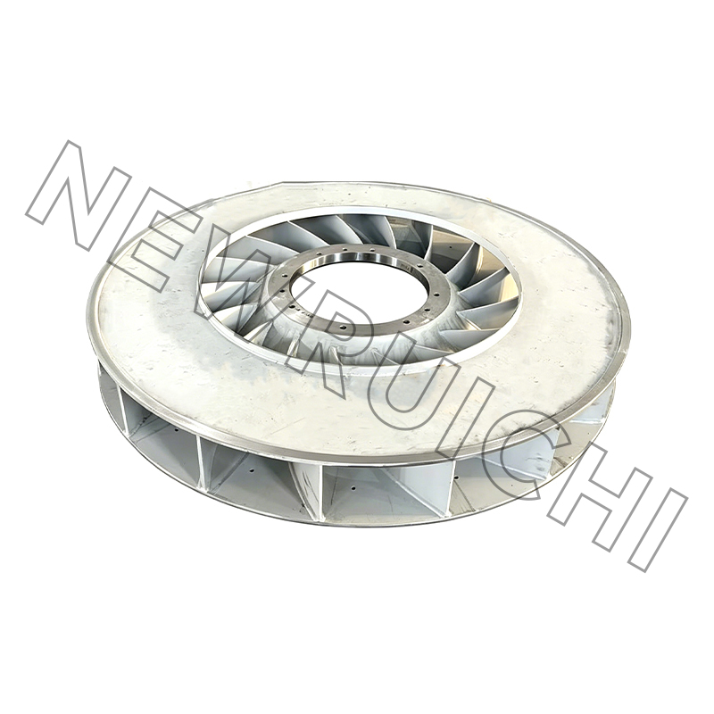 Motor Centrifugal Cooling Fan Forced Convection CoolingSynchronous with the motor shaft, this centrifugal fan provides high-pressure airflow to dissipate heat from windings and core. It reduces temperature rise, enabling motors to operate reliably in continuous-duty and explosive environments.View Product →
Hidden Metrics: Surface Temperature and Thermal Load
The surface temperature of an explosion-proof motor is not a fixed number. It changes with load, ambient temperature, ventilation, and the efficiency of the motor core. The chart below illustrates typical surface temperature trends for three motor construction types at full load in a 40°C ambient. Lower surface temperature means a wider temperature class margin.
These representative values show the hidden cost of running a lower-grade cooling system. A motor that generates more heat forces the designer to select a higher temperature class, which often means a larger frame or a more expensive cooling circuit. In a hazardous area, every degree Celsius of surface temperature margin is valuable.
The efficiency of the manufacturing process for stator and rotor cores also influences heat generation. Laminations with consistent insulation, low burr height, and tight stacking factor produce a motor core with lower iron losses. A well-made core keeps the rotor temp lower and reduces the risk of reaching the ignition point.
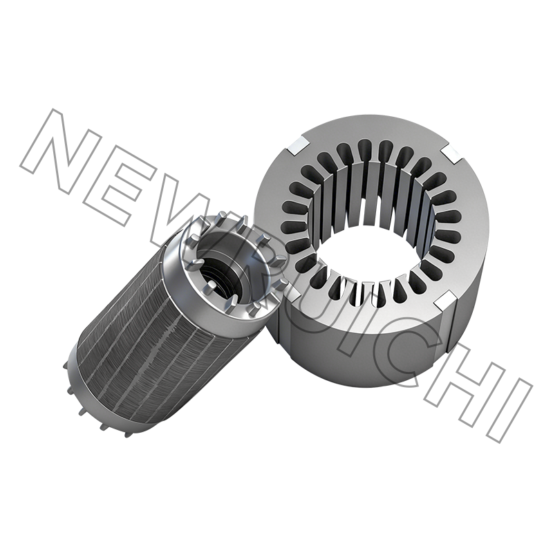
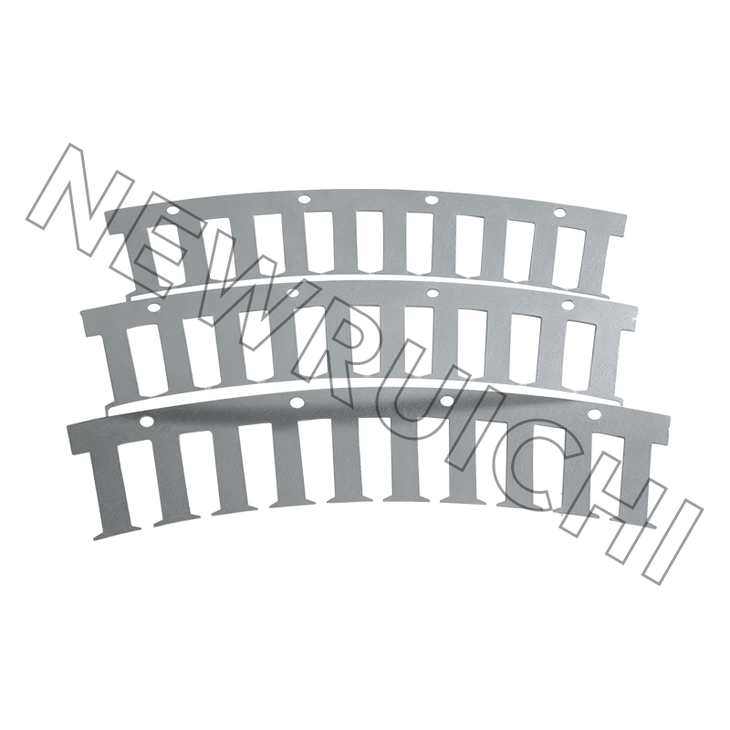 AC Motor Stator and Rotor Core Assembly with Low Loss LaminationsPrecision-stacked silicon steel laminations minimize iron losses and reduce heat generation. This core assembly improves energy efficiency and lowers operating temperature, contributing to safer motor performance in hazardous area applications.View Product →
Industry Applications and Market Distribution
Explosion-proof motors are used in every industry where combustible gases, vapors, or dust are present in the atmosphere. The distribution below shows the relative share of the global demand for hazardous area motors across major sectors.
For motor suppliers, understanding the industry mix is important because each sector has slightly different requirements. Chemical plants focus on corrosive atmospheres and temperature classes. Mining operations require robust frames that resist dust and vibration. Pulp and paper applications emphasize moisture resistance and ease of maintenance. A manufacturer that only offers one standard enclosure might not be able to serve these specialized segments well.
Selection Guide: How to Choose an Explosion-Proof Motor
A structured selection process helps avoid costly mistakes. The following steps should be followed whenever a process engineer or maintenance manager specifies an explosion-proof motor.
Step 1. Classify the zone
Determine whether the area is a gas zone, dust zone, or both. Use the national electrical code or ATEX/IECEx zoning to define the hazardous region.
Step 2. Define the temperature class
Identify the auto-ignition temperature of the specific gas or dust. The motor's T-class must be lower than that value to maintain an acceptable safety margin.
Step 3. Match the enclosure materials
Choose cast iron, steel, or aluminum with corrosion protection suited to the chemical environment. The frame, terminal box, and fan cover must all be compatible.
Step 4. Verify cooling and torque
Check that the cooling method can maintain the required power output while keeping the surface temperature below the temperature class limit. Oversizing is often acceptable, but under-cooling is not.
Step 5. Confirm certifications
Verify that the motor has a valid certificate for the exact zone and gas/dust group. The nameplate must indicate the standard, the certificate number, and the group.
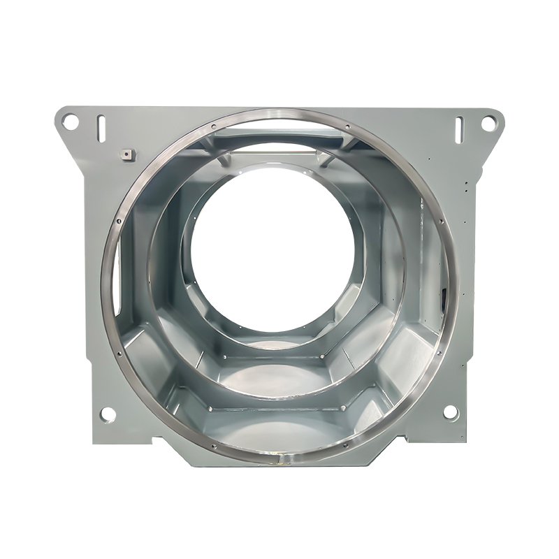
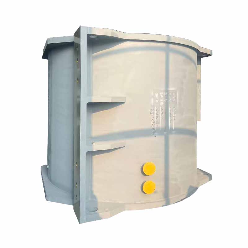
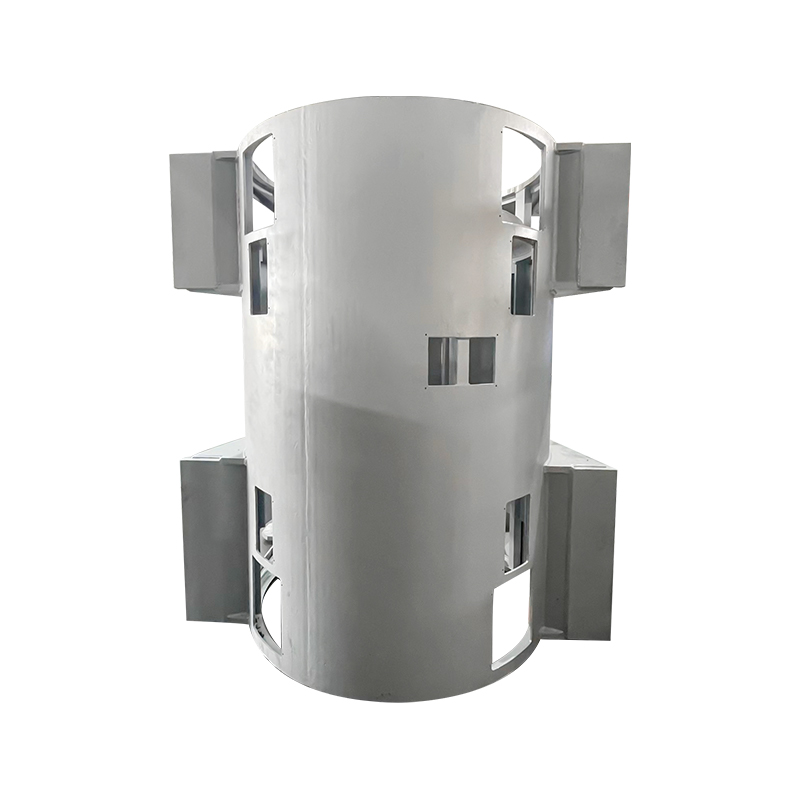
The physical construction of the motor, including the frame and end closures, is just as important as the electrical design. Welded frames that provide rigid support and controlled thermal paths help maintain the flameproof joints over time. Similarly, a motor fan must be designed to move air effectively without creating a secondary spark risk from friction.
Maintenance, Inspection, and Compliance
An explosion-proof motor can only remain safe if it is properly maintained. The following inspection points are critical for compliance and long-term reliability.
- Measure flameproof joint gaps on a regular schedule. A gap that has widened beyond the nameplate tolerance can allow flames to escape.
- Inspect sealing rings and gaskets at the terminal box and cable entries. Poor sealing can undermine the flameproof character of the enclosure.
- Check the motor fan and cooling fins for accumulation of dust or debris. Blocked airflow raises the surface temperature and reduces the safety margin.
- Verify fasteners and bearing housings are torqued to the manufacturer's specification. Loose bolts change the joint pressure and the flamepath length.
- Maintain a documented inspection log that records environmental conditions, load profiles, and temperature readings.
Compliance is not just a paper exercise. When a motor is repaired, the repair shop must follow the original manufacturer's tolerances for machining, welding, and surface finish. Any modification to the enclosure or cooling circuit could void the certification and create a serious safety risk. It is always wise to work with a supplier that has an established quality management system and understands the interplay between frame components, fan systems, and electrical insulation.
Your email address will not be published. Required fields are marked *


 Email: [email protected]
[email protected]
 Telephone/Phone:
+86-18861576796 +86-18261588866
Telephone/Phone:
+86-18861576796 +86-18261588866
+86-15305731515 +86-18861576796
Copyright © Wuxi New Ruichi Technology Co., Ltd. / Wuxi Cailiang Machinery Co., Ltd. All rights reserved.
Stator And Rotor Cores Manufacturers
