 en
en
 русский
 Deutsch
Induction Motor Working Principle: Slip, Torque, and Core Design Explained
A maintenance engineer reads a 55 kW, 4-pole motor nameplate showing 1470 r/min at 50 Hz. A procurement engineer, meanwhile, compares IE3 and IE4 efficiency quotes for the same duty. Both are looking at the same physical story: an induction motor produces torque only because the rotor is always slightly behind the stator's rotating magnetic field. That built-in difference, called slip, is not a design fault — it is the working principle of an induction motor.
Core conclusion: an induction motor works by electromagnetic induction. Three-phase stator windings create a rotating magnetic field; that field induces current in the rotor conductors; the current produces its own magnetic field and, following Lenz's law, the rotor is dragged along behind the field. Because induction requires relative motion, the rotor never catches the field — and this steady slip is what sustains torque.
Everything downstream of this principle — efficiency, core loss, operating temperature, speed control — traces back to how that magnetic field interacts with the stator and rotor cores. Understanding the interaction helps engineers specify motors, and their core components, with more confidence.
Content
- 1 The Working Principle of an Induction Motor, Step by Step
- 2 Construction: Where the Principle Becomes Hardware
- 3 Synchronous Speed, Slip and Torque in Numbers
- 4 Efficiency: Where the Input Power Actually Goes
- 5 Where Induction Motors Carry the Load
- 6 A Sourcing Sequence That Protects Lifecycle Cost
- 7 Maintenance and Compliance
The Working Principle of an Induction Motor, Step by Step
Three-phase induction motors dominate industrial drives because they are self-starting and mechanically simple. When balanced three-phase currents flow through the stator windings, each phase produces a pulsating field; together they form a single magnetic field that rotates around the air gap at synchronous speed:
A 4-pole machine at 50 Hz therefore has a synchronous speed of 1500 r/min; at 60 Hz the same machine has 1800 r/min. Four effects then convert that rotating field into shaft torque.
Synchronous speed
Fixed by supply frequency and pole count, not by load. The field always rotates at Ns; the rotor does not.
Transformer action
The rotor is effectively a short-circuited secondary winding. Current is induced into it exactly as in a transformer, but inside a rotating air-gap field.
Lenz's law
The induced rotor current opposes the change that created it. The mechanical result is a torque pulling the rotor in the direction of the rotating field.
Slip
Defined as s = (Ns - N) / Ns. Full-load slip is typically 1% to 8%; higher slip under load means higher rotor resistance or an overloaded machine.
No brushes, slip rings in the cage design, or permanent magnets are required. That simplicity lowers rotor inertia and eliminates brush wear — two reasons induction motors remain the default for constant-speed pumps, fans, compressors and conveyors.
Construction: Where the Principle Becomes Hardware
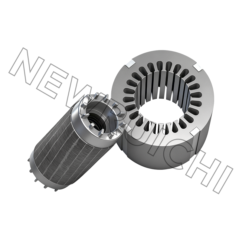
The stator core is a stack of thin silicon steel laminations with slots for the three-phase windings. The rotor of a squirrel-cage machine uses a similar lamination stack, with aluminum or copper bars cast into the slots and short-circuited by end rings. A wound-rotor machine instead carries windings brought out to slip rings, which allows external resistance to shape the torque curve.
Lamination grade and thickness set the iron-loss baseline. Line-frequency motors typically use 0.35 mm or 0.50 mm non-oriented silicon steel; thinner sheets reduce eddy currents because each layer contains a smaller secondary loop. An insulating coating between sheets blocks interlaminar current, and burr height from punching is controlled because burrs create conductive bridges between layers. The air gap, meanwhile, is kept as small as mechanical tolerances allow — magnetizing current rises sharply as the gap grows.
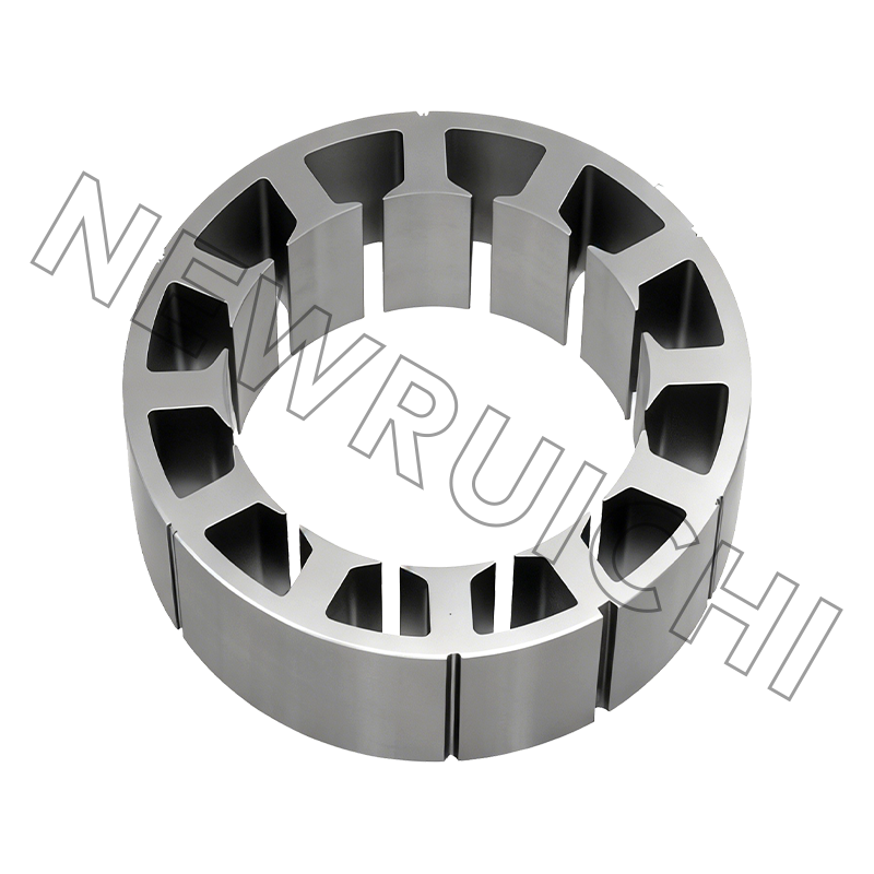
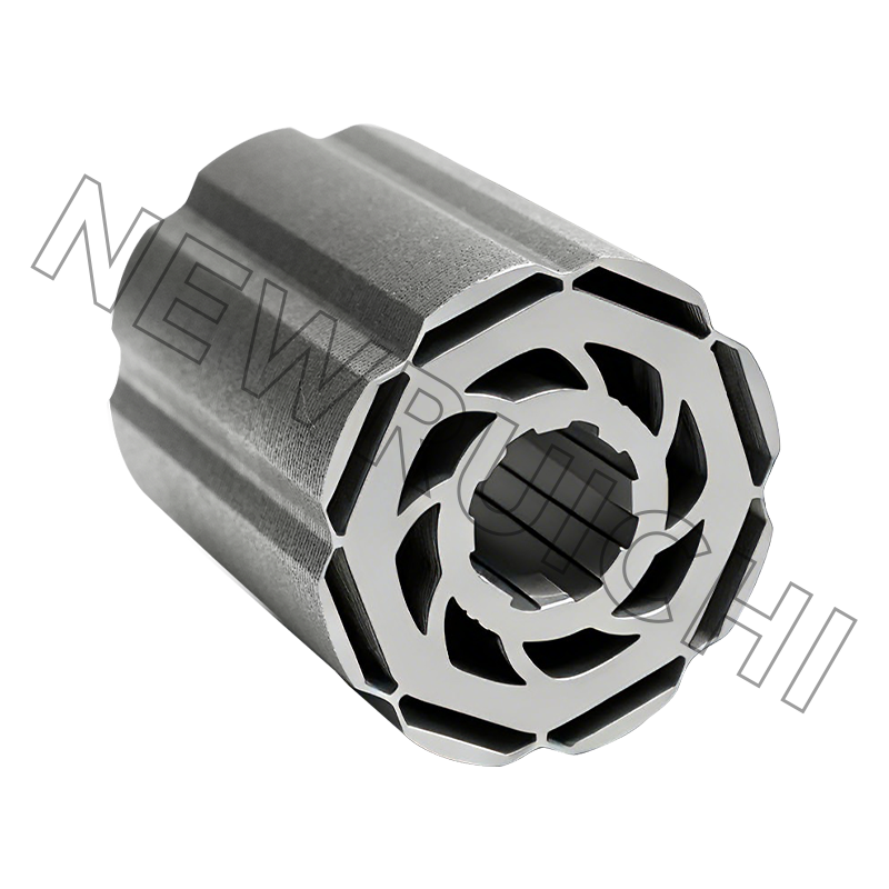
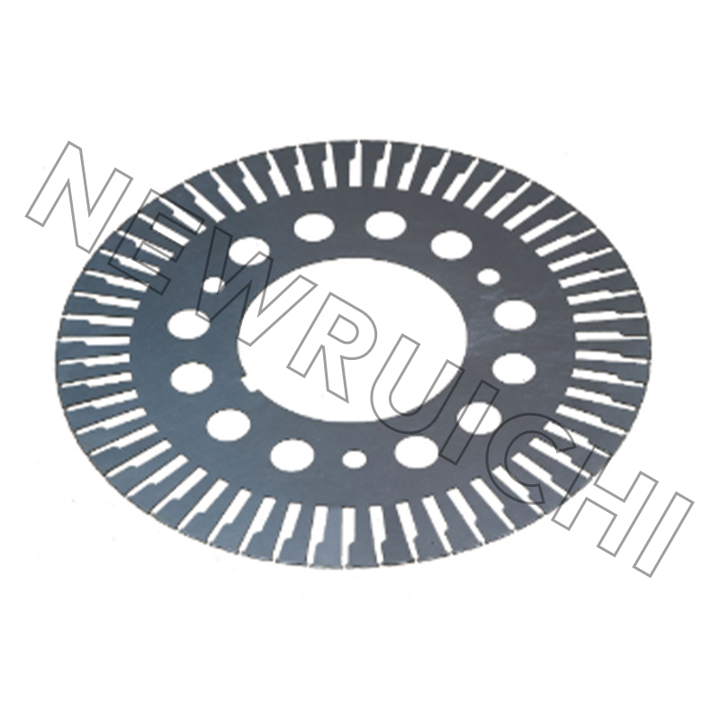 AC Motor Stator and Rotor Laminations for Efficient Core ManufacturingThese precision-stamped non-oriented silicon steel laminations control burr height and thickness to reduce iron loss, supporting stable motor operation in industrial, HVAC, and energy applications.View Product →
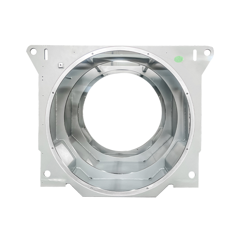
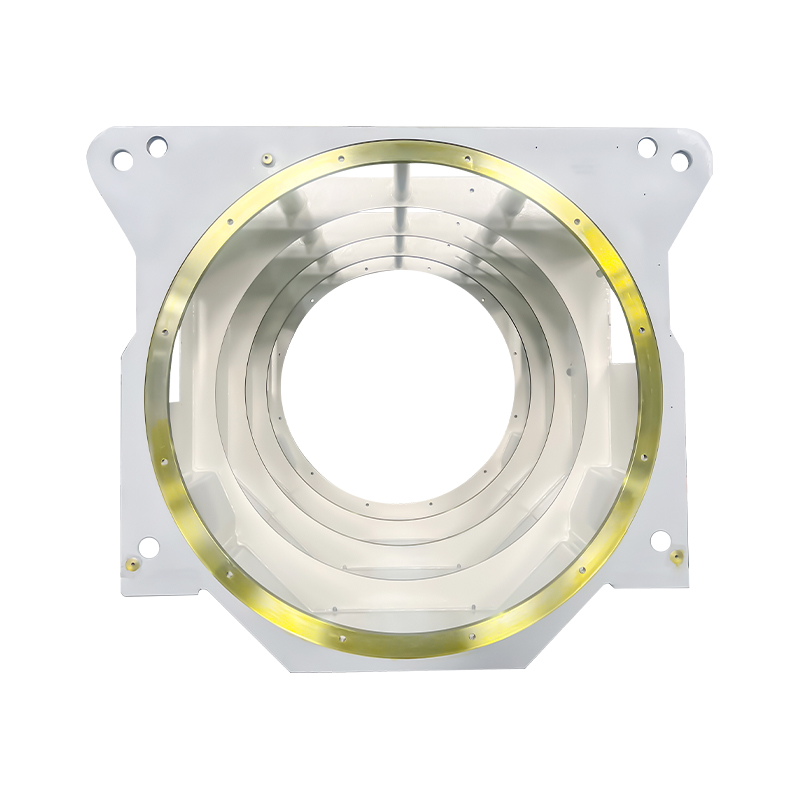
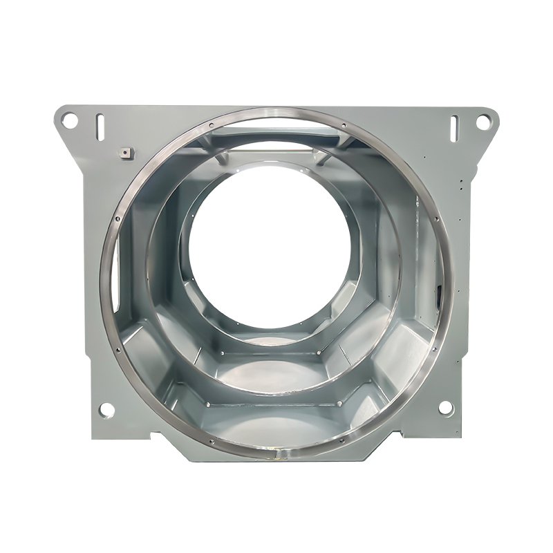
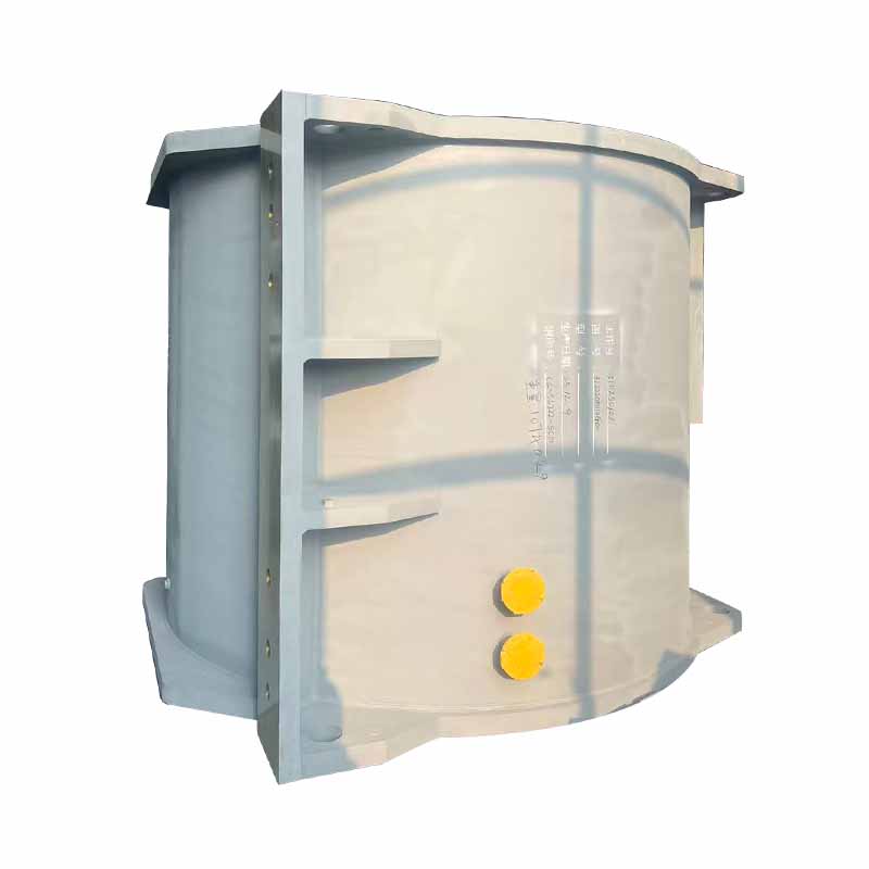
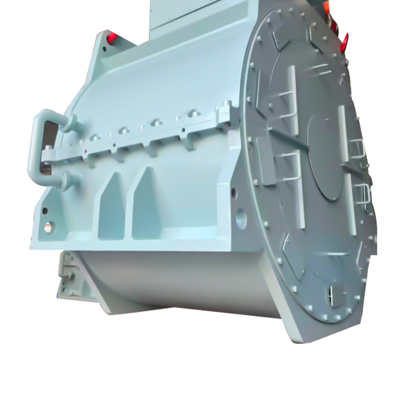
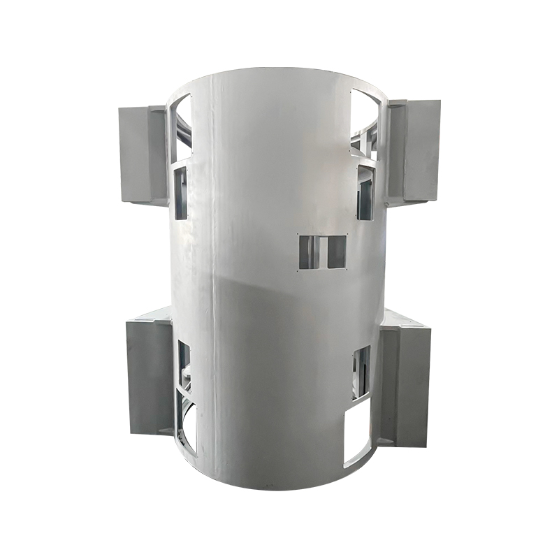
For a closer look at how the two parts interact, see our earlier discussion of how a stator and rotor work in an electric motor. The frame, end shields, bearings and cooling fan complete the machine; in welded box-type frames used for wind, marine and high-voltage motors, the housing also has to manage vibration and cooling.
Synchronous Speed, Slip and Torque in Numbers
Slip works as both a rating parameter and a diagnostic signal. If a motor draws more current than nameplate while running slower at full load, the usual suspects are reduced supply voltage, increased rotor resistance, or an overloaded shaft.
During a direct-on-line start, slip equals 1 and the rotor is momentarily at line frequency, which is why starting current reaches five to eight times rated current. Variable frequency drives control speed by changing supply frequency and voltage together, holding the core flux near its design point and keeping slip inside its intended window. Because the machine always draws magnetizing current to establish the field, power factor is below 1; a larger air gap or a lower-quality core increases that magnetizing current and worsens it further.
Efficiency: Where the Input Power Actually Goes
A well-built low-voltage induction motor converts roughly 90% to 96% of input power into shaft power, depending on rating, pole count and efficiency class. The remaining losses are concentrated in a few places.
Iron loss is the second largest block, and the one most directly tied to core material and core manufacturing. High-grade non-oriented silicon steel, clean punching with controlled burr height, consistent stacking pressure, and a durable interlaminar coating all reduce magnetizing current and core temperature. On motors that run more than 6000 hours per year, a 1% efficiency gain can pay for the core many times over — which is why many motor makers now specify finished motor core assemblies rather than raw stampings. When auditing a core supplier, it pays to understand the full process chain; our manufacturing overview shows how material, stamping and stacking work together in practice.
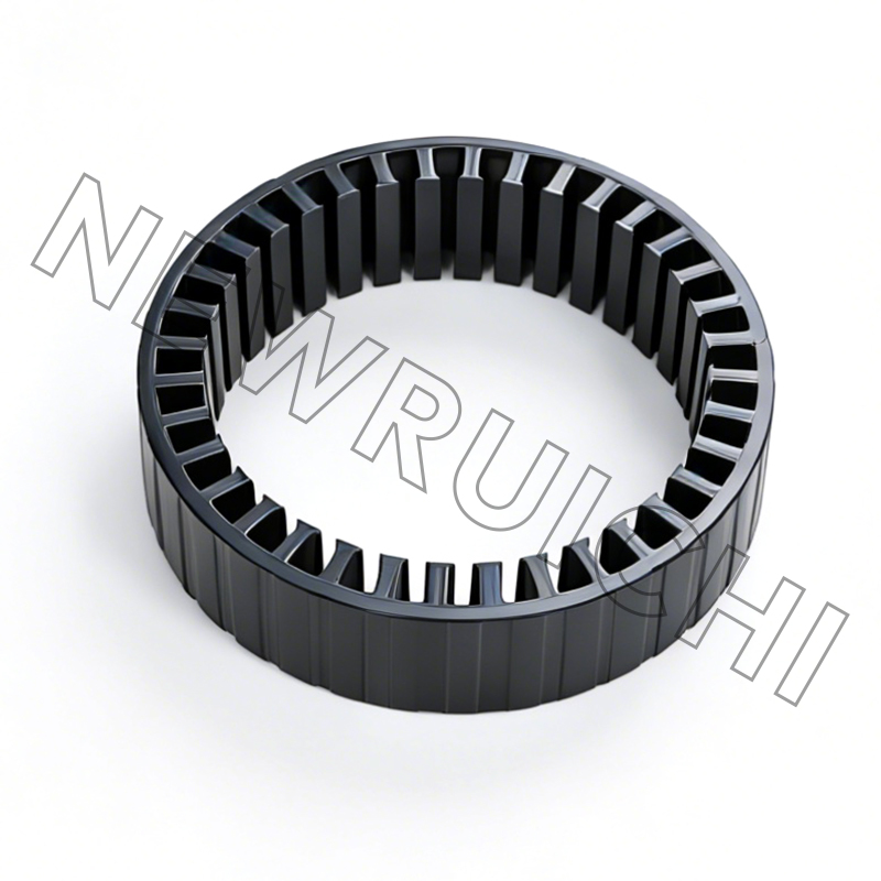
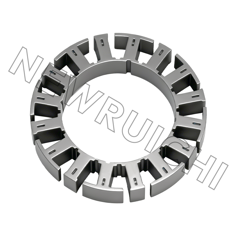
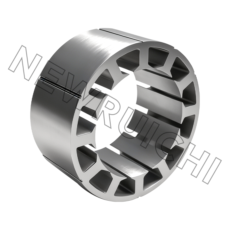
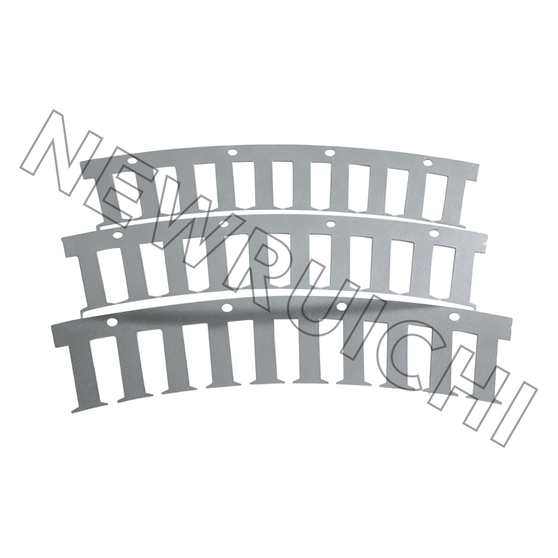 Finished AC Motor Stator and Rotor Core AssembliesPre-stacked and bonded core assemblies reduce magnetizing current and core temperature, helping motor makers gain efficiency and cut losses in high-run-hour applications like pumps and compressors.View Product →
Where Induction Motors Carry the Load
Electric motor systems consume roughly 45% of industrial electricity worldwide, and induction machines make up the largest share of that installed base. The application split is uneven, and each sector puts a different weight on the same working principle.
- Pumps and fans — 30%
- Compressors and HVAC — 25%
- Conveyors and material handling — 18%
- Machine tools — 12%
- Other (marine, wind, traction) — 15%
The pattern repeats across wind, marine and high-voltage industrial machines: the electromagnetic core sets the efficiency, while the frame manages the environment. Welded box-type frames with integrated cooling ducts handle the mechanical load in large generators; the same machine can have very different housings depending on whether it sits in a nacelle, a pump room or a ship's hull.
A Sourcing Sequence That Protects Lifecycle Cost
For engineers buying complete motors, or buying cores for in-house motor production, a structured sequence turns a vague specification into an auditable decision.
Define the operating profile. Speed, torque, duty cycle, ambient temperature and altitude set the true requirement before any component is chosen.
Lock the efficiency class and enclosure. IE3 or IE4, IP rating and cooling method together fix the loss budget that the core must satisfy.
Match material and core process. Silicon steel grade, lamination thickness, coating type and joining method — adhesive bonding, interlocking, or laser/TIG welding — are chosen together, not separately.
Validate with prototypes. Measure magnetizing current, iron loss and noise on sample cores before authorizing full production.
Qualify the supplier. Review quality systems, process control and delivery performance before committing volume orders.
The material step is where most of the lifetime loss cost is decided; selecting a high-grade non-oriented silicon steel pays back through lower iron loss in every operating hour.
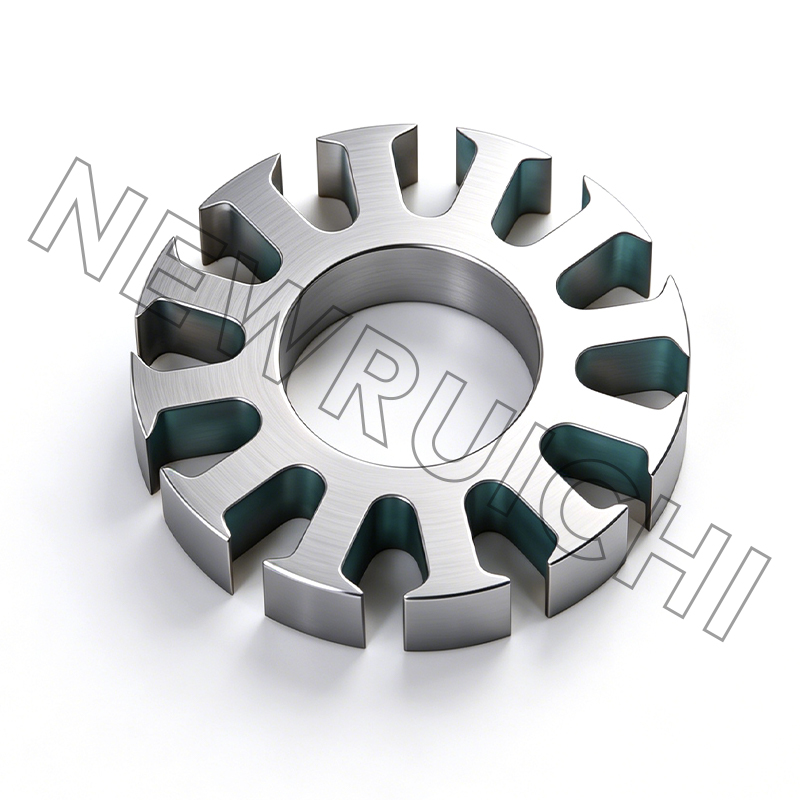
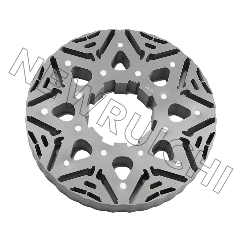
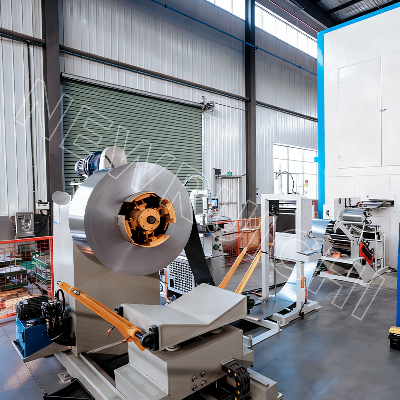 High-Grade Non-Grain-Oriented Silicon Steel CoilsThis low core-loss NGO steel improves motor efficiency and lowers operational costs, with customized widths and surface treatments for continuous stamping lines and demanding electromagnetic applications.View Product →
The point of the sequence is to make efficiency, cost and delivery risk explicit before purchase orders are written rather than after.
Maintenance and Compliance
Induction motors are robust, but they reward a disciplined maintenance routine. The three signals that catch developing faults early are temperature, vibration and bearing condition.
- Keep ventilation paths clear; blocked cooling raises winding temperature and accelerates insulation aging.
- Check supply voltage balance; even a few percent of unbalance increases losses and heating.
- Trend insulation resistance and vibration instead of reacting to alarms.
- For VFD-fed motors, confirm the insulation system is inverter-rated.
Efficiency regulation is also tightening. IEC 60034-30-1 defines the IE1 to IE4 classes, and many markets now require IE3 or better for line-fed motors, with IE4 growing in premium segments. That pressure flows directly into the core supply chain: lower-loss silicon steel, controlled burr height, verified interlaminar coatings and consistent stacking quality. Standards such as ISO 9001 and IATF 16949 give buyers a baseline for auditing that consistency in a supplier's process.
Mechanically, an induction motor is a simple machine. Electrically, it is a chain of induction events: a rotating field, an induced current, an opposing force, and a steady slip that converts electrical input into shaft torque. For anyone who specifies, maintains or supplies the cores inside those machines, that chain is the most useful map to better efficiency and lower total cost.
Your email address will not be published. Required fields are marked *


 Email: [email protected]
[email protected]
 Telephone/Phone:
+86-18861576796 +86-18261588866
Telephone/Phone:
+86-18861576796 +86-18261588866
+86-15305731515 +86-18861576796
Copyright © Wuxi New Ruichi Technology Co., Ltd. / Wuxi Cailiang Machinery Co., Ltd. All rights reserved.
Stator And Rotor Cores Manufacturers
