 en
en
 русский
 Deutsch
Induction Motor vs Synchronous Motor: Key Differences Explained for Engineers
Bottom line: An induction motor is the more forgiving, self-starting workhorse for general industrial drives. A synchronous motor is the better choice when speed must remain exact, when the grid needs power-factor support, or when the extra first cost can be recovered through efficiency gains under stable load.
Content
Working Principle: Slip Is the Boundary Line
Both motor types are AC machines that generate a rotating magnetic field in the stator. The difference lies in how the rotor responds to that field.
In an induction motor, the stator field induces current in the rotor conductors. The rotor must run slightly slower than the field to maintain that induced current; this speed difference is called slip. Typical full-load slip is 1% to 5%, which is why an induction motor running a pump or fan changes speed slightly with load.
In a synchronous motor, the rotor is either permanently magnetized, electromagnetically excited, or built with reluctance poles. Once the rotor reaches the same speed as the rotating field, it locks in and turns at exactly synchronous speed: Ns = 120f/p, where f is supply frequency and p is the number of poles. Slip is zero, regardless of load, within the motor's pull-out torque limit.
Induction Motor Traits
- Self-starting when the stator is energized
- Simple squirrel-cage or wound rotor
- Small speed variation with load
- Lagging power factor, usually 0.82 to 0.88
- Robust in harsh environments
Synchronous Motor Traits
- Constant speed from no load to full load
- Requires damper winding, VFD, or external start in many designs
- Permanent magnet, wound-field, or reluctance rotor
- Can operate at unity or leading power factor
- Higher steady-state efficiency for large drives
Construction and Starting Behavior
The stator looks similar in both machines: slotted laminations, copper or aluminum windings, and a frame designed for cooling by fan, water, or air-to-water heat exchanger. The rotor is where the designs diverge.
An induction rotor is a stack of electrical steel laminations with embedded bars, short-circuited by end rings, or a wound rotor connected to external resistors through slip rings. There are no magnets and no separate excitation source. This construction makes the motor naturally capable of starting against a heavy load, because the induced rotor current creates torque as soon as the stator field rotates.
A synchronous rotor can be a solid cylindrical rotor with field windings supplied by an exciter, a laminated salient-pole rotor, or a permanent-magnet rotor. A smooth-rotor wound-field synchronous machine normally cannot start from a standstill on its own; the rotating stator field at 50 Hz or 60 Hz is too fast for the rotor to follow. Practical designs add a damper winding for line starting or require a variable-frequency drive to accelerate the rotor from near-zero speed.
This starting difference has direct consequences for the control cabinet and the mechanical driveline. An induction motor can often connect directly to the line with only a starter or soft-starter. A line-started synchronous motor needs excitation control and a damper bar circuit; a VFD-fed synchronous motor needs position feedback for permanent-magnet machines. Engineers therefore price the whole drive system, not just the motor nameplate.
Head-to-Head Performance Comparison
Hidden Performance Indicators and Efficiency
The first comparison table shows the headline differences, but selection often comes down to numbers that are not on the datasheet: slip losses, pull-out torque, rotor temperature sensitivity, reactive power draw, and the quality of the stator and rotor core.
At full load, a modern synchronous motor can deliver around two to three points of efficiency advantage over an induction motor of the same frame. The gap widens at partial load because induction rotor losses fall with slip, but the magnetizing current stays constant. The simple bar chart below shows a representative full-load efficiency comparison for a medium-size industrial drive.
Efficiency alone does not always justify the price premium. A synchronous motor is a better investment when the annual operating hours are high, the load is steady, and the plant can use leading reactive power to reduce power-factor penalties. In applications with wide load swings, the simpler induction motor may produce nearly the same annual energy cost with lower first cost and easier service.
There are also less obvious limits. A permanent-magnet synchronous rotor can demagnetize if the motor is forced to run above its rated temperature for long periods. A wound-field synchronous rotor needs excitation control, and a sudden short circuit can produce very high mechanical stress. Induction rotors handle overload more gracefully because they have no permanent magnets and no slip-ring excitation, though the rotor bars can fracture in repetitive high-torque starts.
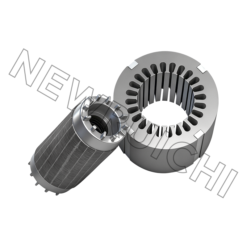
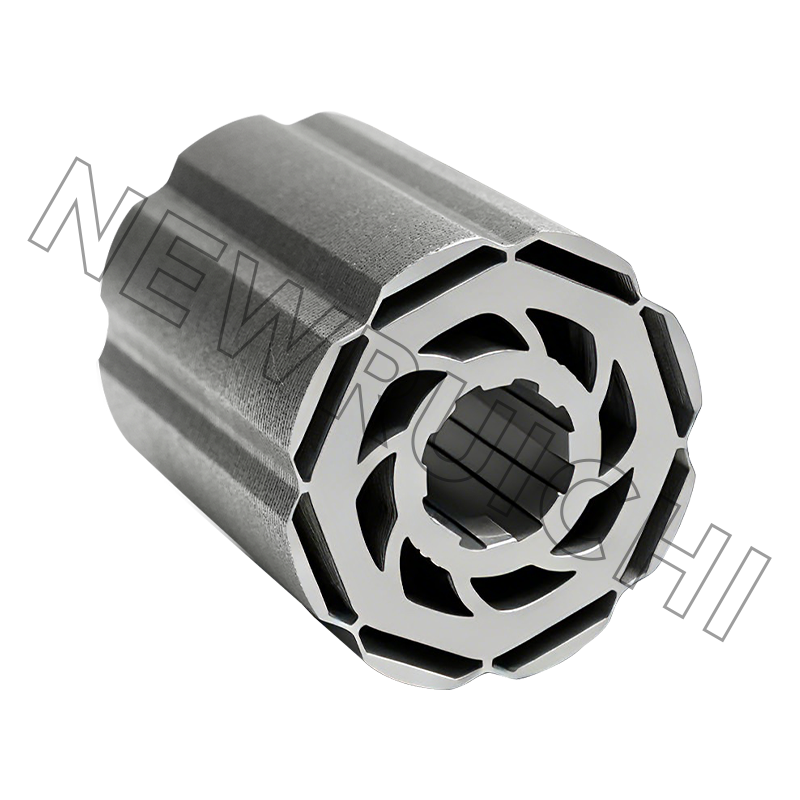
Core loss is another hidden variable. Both motor types depend on low-loss electrical steel and tight control of the air gap. This is why motor builders evaluate laser-TIG welded laminated core assemblies during prototype validation: stacking method, lamination thickness, and burr height directly affect eddy-current loss and noise. You can read more about the role of the stator and rotor in an electric motor or inspect motor core manufacturing capabilities before approving a supplier.
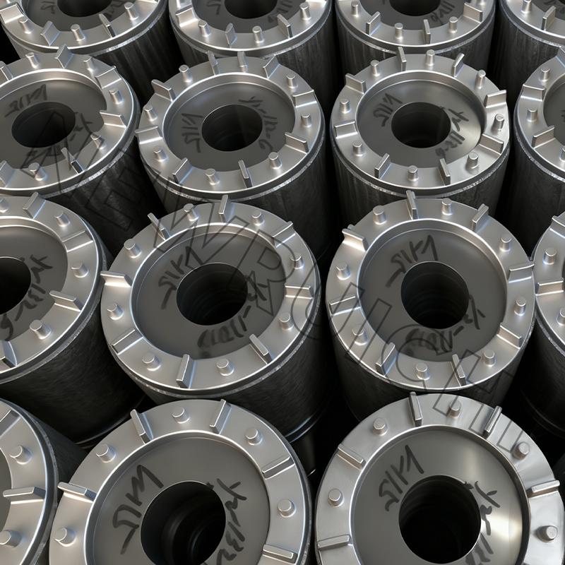 Laser/TIG-welded Laminated Core Suppliers, Company - Wuxi New Ruichi Technology As Laser/TIG-welded Laminated Core Suppliers and Company in China, New Ruichi/Cailiang offer Wholesale Laser/TIG-welded Laminated Core on...View Product →
Industry Application Distribution
In general manufacturing, induction motors still dominate the installed base because pumps, fans, conveyors, and machine tools do not require absolute speed lock. Synchronous machines appear where speed precision, high torque, or power-factor correction matters.
- Industrial pumps, fans, compressors: roughly 55% induction
- Precision drives, elevators, large compressors: about 20% synchronous
- Traction and electric vehicles: about 15% synchronous permanent-magnet
- Textile, cement, and special-purpose machines: 10% mixed
The distribution shifts when the application is above several megawatts. Large compressor trains, ball mills, and some marine propulsion systems use synchronous motors because the efficiency gain over ten years dwarfs the initial price gap.
Selection and Total-Cost Guide
Use a short decision path rather than a general rule. The right motor fits the load profile, the electrical system, and the maintenance team.
Define the speed requirement
If the process cannot tolerate slip, choose a synchronous motor. If a few percent of speed change is acceptable, induction is usually sufficient.
Check starting torque
Induction motors give strong, natural starting torque. A synchronous motor may need a VFD or damper winding to accelerate to synchronous speed without excessive current.
Evaluate power factor and utility charges
A synchronous motor with field control can supply leading reactive power and reduce demand penalties. An induction motor will always draw lagging current, which may require capacitor banks.
Model the lifecycle cost
Compare purchase price, drive cabinet, energy consumption, maintenance, spare parts, and expected downtime. For machines running over 6,000 hours per year, the efficiency gap often pays back within three to five years.
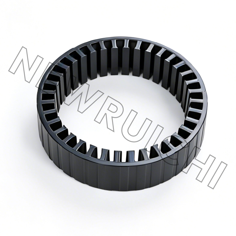
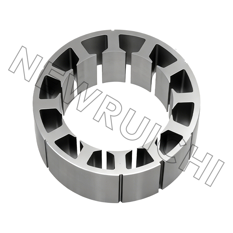
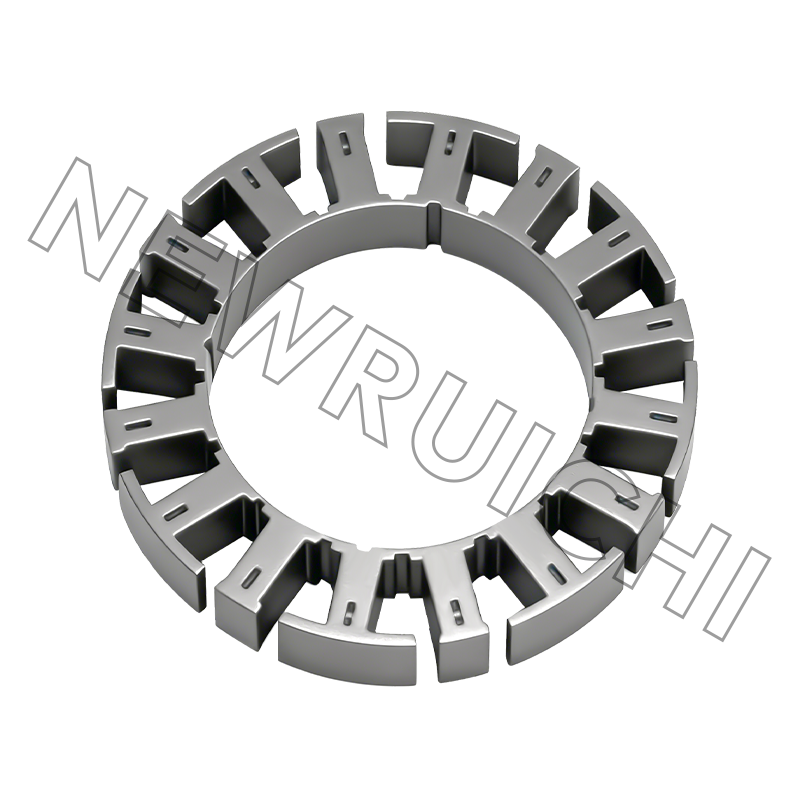
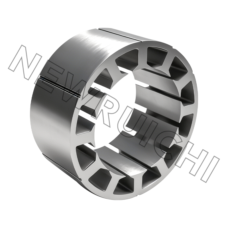
When the motor is part of a manufactured product, the core supplier decision matters as much as the motor type. A well-designed AC motor stator and rotor core assembly reduces iron loss and improves torque consistency, especially for motors that will be paired with a VFD.
 AC Motor Stator and Rotor Core Assembly Suppliers, Company - Wuxi New Ruichi TecAs AC Motor Stator and Rotor Core Assembly Suppliers and Company in China, New Ruichi/Cailiang offer Wholesale AC Motor Stator and Rotor ...View Product →
Maintenance, Compliance, and Core Quality
Maintenance strategies differ because the failure modes are different. An induction motor mostly fails in bearings, winding insulation, or rotor bars. A synchronous motor adds excitation failures, brush wear in older designs, and magnet-related issues in permanent-magnet rotors. For brushed synchronous motors, schedule regular slip-ring and brush inspection; for PM machines, follow strict rotor handling procedures to avoid magnet chipping and demagnetization.
From a compliance standpoint, industrial purchasers commonly verify IEC 60034 or NEMA MG1 performance, IE3/IE4 efficiency classes, and harmonic limits when VFDs are used. Motor rebuilders and original equipment manufacturers also need consistent material certificates, dimensional inspection, and traceability for the stator and rotor lamination stack.
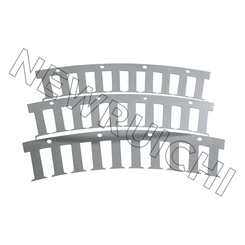
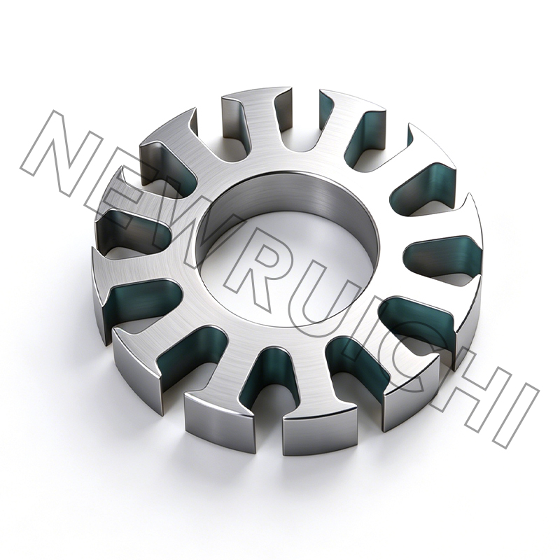
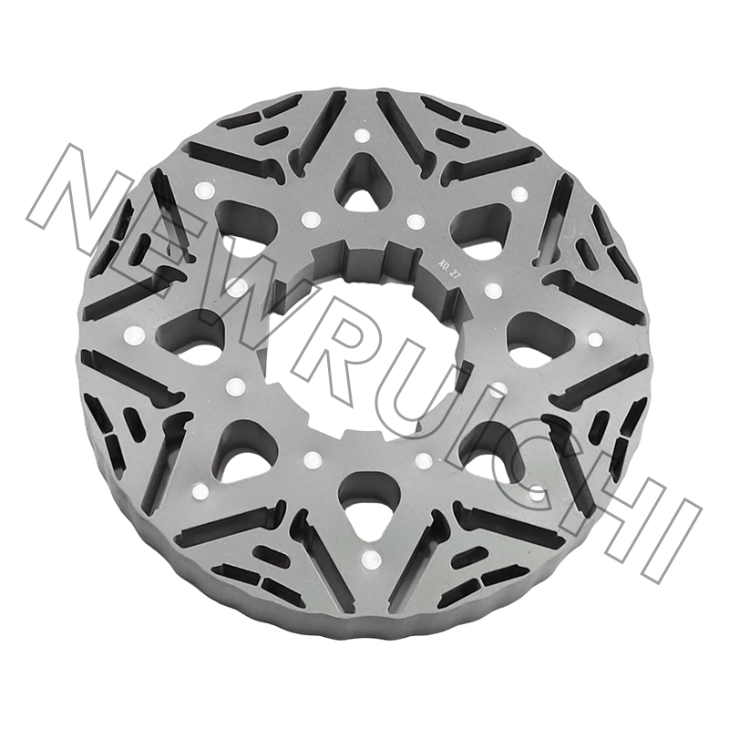
Core quality is not cosmetic. Lamination thickness, burr height, annealing quality, and joining method all affect core loss, build factor, and vibration. That is why many motor engineers specify high-grade non-oriented silicon steel for prototype builds and production runs. A supplier with controlled electrical steel grades, laser or welded core manufacturing, and sample validation can shorten the development cycle at both the prototype and serial-production stages.
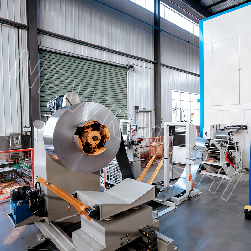 High Grade Non-grain-oriented (NGO) Silicon Steel Suppliers, Company - Wuxi New As High Grade Non-grain-oriented (NGO) Silicon Steel Suppliers and Company in China, New Ruichi/Cailiang offer Wholesale High Grade Non-g...View Product →
For a final check, keep three documents ready: the motor datasheet with efficiency measured according to the relevant standard, the test certificate for power factor and slip, and the core supplier's inspection report. These documents separate a reliable drive system from one that looks good on paper but underperforms on the production floor.
The induction versus synchronous motor decision is not about which technology is newer. It is about what the process requires: slip tolerance, exact speed, power factor, starting torque, and long-term energy cost. Match the motor to the load, verify the system cost, and check the quality of the magnetic core before making a final purchase.
Your email address will not be published. Required fields are marked *


 Email: [email protected]
[email protected]
 Telephone/Phone:
+86-18861576796 +86-18261588866
Telephone/Phone:
+86-18861576796 +86-18261588866
+86-15305731515 +86-18861576796
Copyright © Wuxi New Ruichi Technology Co., Ltd. / Wuxi Cailiang Machinery Co., Ltd. All rights reserved.
Stator And Rotor Cores Manufacturers
