 en
 русский
 Deutsch

Difference Between Single-Phase and Three-Phase Motors: Sizing and Efficiency
A 2.2 kW borehole pump fails on a farm that already has a 400 V three-phase supply. The maintenance file lists a single-phase replacement, so a single-phase unit is ordered and installed. Two months later the run capacitor is bulging, the pump-house cable is running warm at close to 15 A, and the motor trips on thermal overload during long draws. Nothing was wrong with the motor. The specification was.
The difference between a single-phase and a three-phase motor is not a label on a nameplate. It changes the starting torque, the current per kilowatt, the frame size that fits the bracket, the cable you must pull, and the maintenance items you will be buying for the next ten years.
The conclusion, before the physics
- If a three-phase supply exists and the shaft load is above roughly 1.1 to 1.5 kW, choose three-phase. It is smaller, lighter, more efficient, self-starting, and usually cheaper per kilowatt.
- Choose single-phase only when the supply is genuinely single-phase, the rating is below about 3.7 kW, or the duty is intermittent and small, such as a domestic pressure set, a fan, or a gate motor.
- Never compare the two by kilowatt rating alone. Compare line current, starting current, starting torque, frame size, and the cost of the auxiliary parts the single-phase unit needs.
Content
Why the Two Designs Behave Differently
Both machines are induction motors with a squirrel-cage rotor and a laminated stator core. The difference sits almost entirely in the stator winding and in what the supply does to it.
Three-phase: a field that already rotates
Three windings spaced 120 electrical degrees apart, fed from a three-phase supply, produce a flux wave that rotates at synchronous speed (120 times frequency divided by pole count). The rotor sees a moving field from standstill, so torque is available at zero speed with no auxiliary device at all. Torque is essentially constant through each electrical cycle, which is why three-phase machines run quietly and hold load smoothly at low speed.
Single-phase: a pulsating field that must be tricked into rotating
One winding on a single-phase supply produces a pulsating flux, which mathematically splits into two counter-rotating fields of equal strength. At standstill they cancel, so net starting torque is zero. The industry solves this with an auxiliary winding displaced about 90 electrical degrees, plus a capacitor (capacitor-start, capacitor-run, or permanent split capacitor), a start relay, or a shaded pole for tiny sizes. Once the rotor reaches roughly 70 to 80 percent of speed, a centrifugal switch or relay drops the auxiliary circuit out.
Two consequences follow. First, torque still pulsates at twice line frequency, so single-phase motors vibrate more and are noisier at the same output. Second, current per kilowatt is roughly three times higher at 230 V than an equivalent three-phase motor draws at 400 V, which drives cable size, contactor rating, and voltage drop over long runs.
Starting torque
Capacitor-start single-phase units reach 1.5 to 3.0 times full-load torque; three-phase direct-on-line units reach 1.8 to 2.5 times with far simpler control gear.
Rating ceiling
Single-phase designs rarely go above 3.7 kW because capacitor, switch, and cable costs climb faster than motor cost. Three-phase covers 0.09 kW to 1000 kW in standard frames.
Frame and weight
For the same output, a three-phase motor is typically one to two IEC frame sizes smaller and 20 to 30 percent lighter, which matters when the mounting bracket is already fixed.
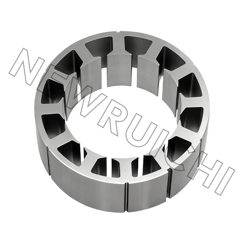
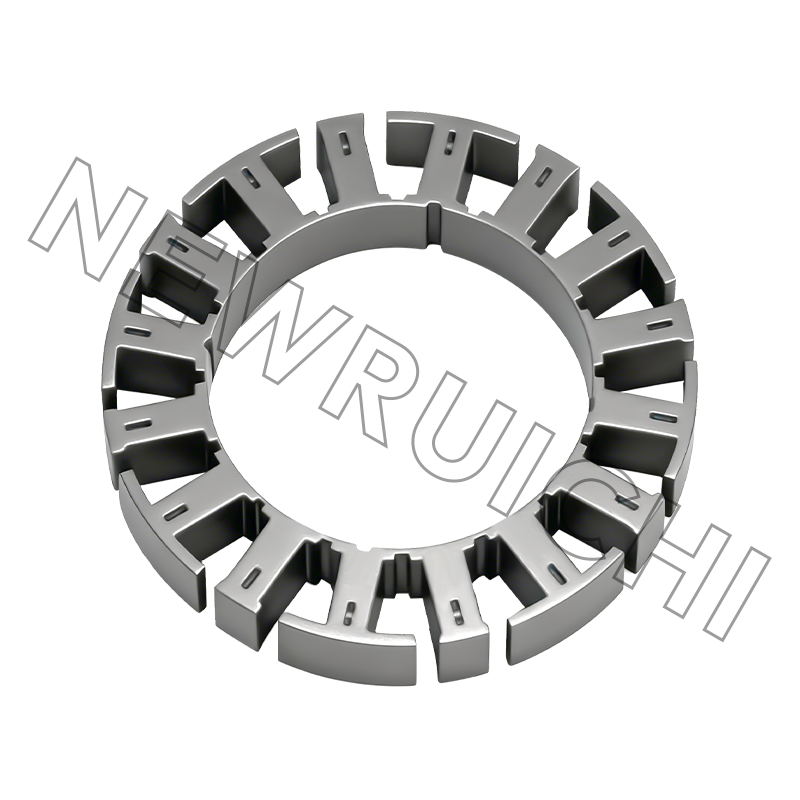
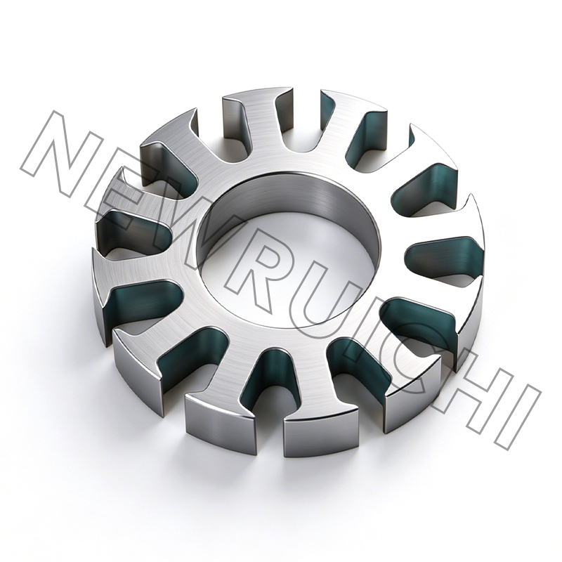
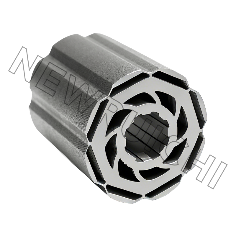
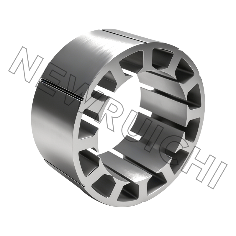
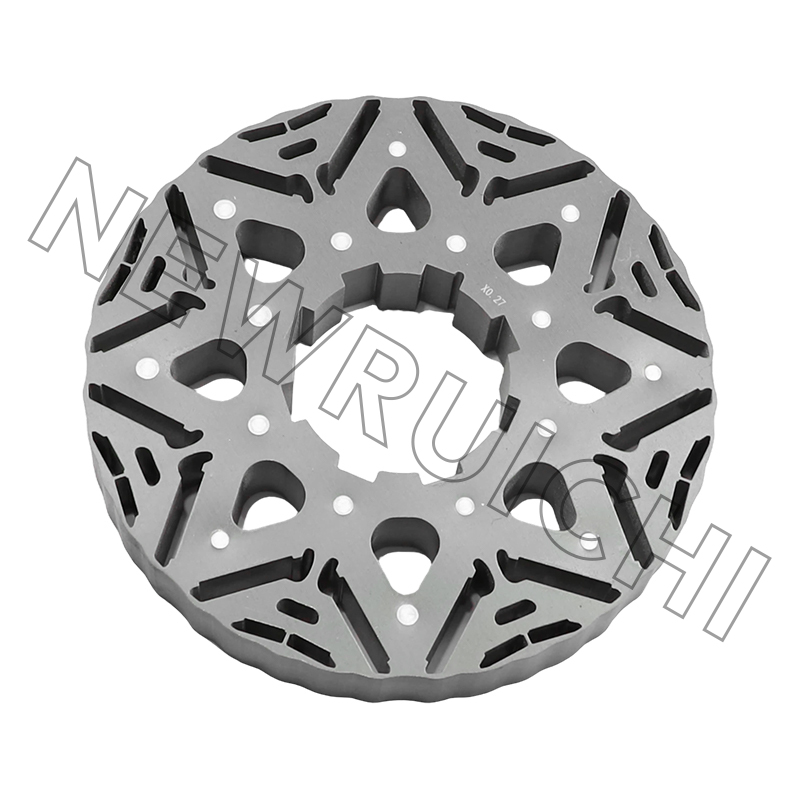
The lamination design follows the winding. A single-phase stator usually splits its slots roughly two-thirds main winding and one-third auxiliary, while a three-phase stator uses a distributed 60-degree phase belt with balanced slot allocation. That changes slot count, tooth width, and the copper-to-iron ratio inside the same outside diameter. If you want the winding theory in more depth, this explanation of how a three-phase motor works walks through the field, slip, and core side of the design.
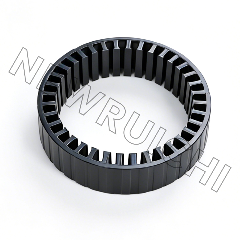
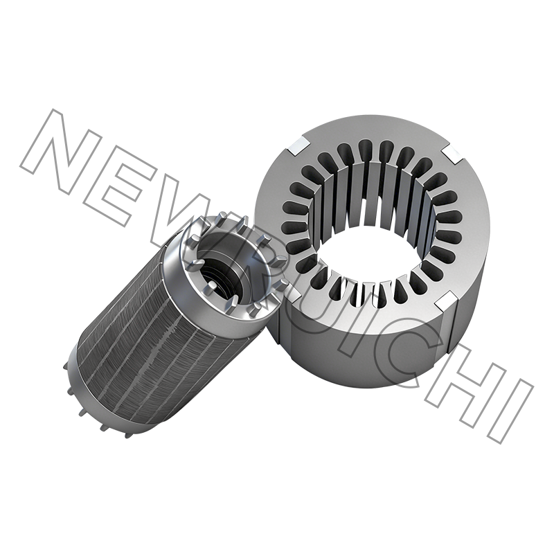
 AC Motor Stator and Rotor Core AssemblyPrecision-stacked silicon steel stator and rotor cores for AC motors, designed to support efficiency, low noise, and stable torque in industrial applications.View Product →
Side-by-Side Comparison of Real Specifications
The table below reflects typical values for 4-pole, 50 Hz industrial motors under 5 kW, drawn from common catalogue data and IEC efficiency classes. Treat the ranges as a screening tool, then confirm with the manufacturer's test sheet.
The Efficiency Gap, Measured by Rating
The efficiency advantage of three-phase is not a fixed number. It is largest at small ratings, where the auxiliary winding, capacitor losses, and higher current density hurt single-phase designs most, and it narrows as frames get bigger.
- Light green bars: single-phase capacitor-run motors, typically 68 to 80 percent at these ratings.
- Dark green bars: three-phase IE3 motors, from about 80 percent at 0.75 kW to almost 88 percent at 3.7 kW.
- At 0.75 kW the gap is roughly 12 points; at 3.7 kW it is closer to 8 points. On a pump running 4000 hours a year, that is the difference between two electricity bills, not two percentages.
Note that IEC 60034-30-1 efficiency classes apply to three-phase machines; single-phase motors sit outside that classification, so a catalogue cannot be compared class-for-class. Ask for measured test data instead, and check the grade, thickness, and stacking factor of the electrical steel behind those numbers.
Where Single-phase Motors Still Belong
Single-phase demand is concentrated in equipment that plugs into a domestic or light-commercial supply. The split below is an indicative read of small motor applications rather than a market census, but it matches what most procurement teams see in this segment.
- 30 percent: domestic water pumps, pressure sets, and small irrigation units.
- 25 percent: fans, ventilation, and air-handling units under 1.5 kW.
- 18 percent: refrigeration and small reciprocating compressors.
- 14 percent: workshop machinery, bench tools, and light conveyors.
- 13 percent: shutters, gate motors, and other intermittent duty drives.
Where those same duties are served inside a plant with three-phase distribution, the three-phase version is almost always specified, even at 0.37 kW, because a smaller frame, longer life, and standard overload protection outweigh the small price difference.
A Practical Selection Sequence
- Confirm the supply at the terminal box, not on the drawing. Measure line voltage and check whether neutral is present. A 230 V single-phase motor on a 400 V three-phase supply needs a different starter, not a different motor.
- Size on torque, not kilowatts. A load that starts under full load, such as a loaded conveyor or a positive-displacement pump, may need a capacitor-start single-phase unit at twice the nameplate rating or a three-phase unit with a soft starter.
- Count starts per hour. Frequent starting is hard on capacitors and centrifugal switches. Above roughly six to eight starts per hour, three-phase with a VFD is the more durable choice.
- Match the mechanical interface. Check frame, flange, shaft, and terminal box position against the existing bracket before ordering, because a smaller three-phase frame will not bolt onto a single-phase foot pattern without an adapter.
- Fix the core specification. Electrical steel grade, lamination thickness, stacking factor, and the interlock or welded construction decide the losses and the noise floor. Our core and frame manufacturing overview explains how stamping, stacking, and welding choices affect the finished result.
- Collect the documents. Efficiency class, insulation class, IP rating, test report, and quality certification should arrive before the goods, not after commissioning.
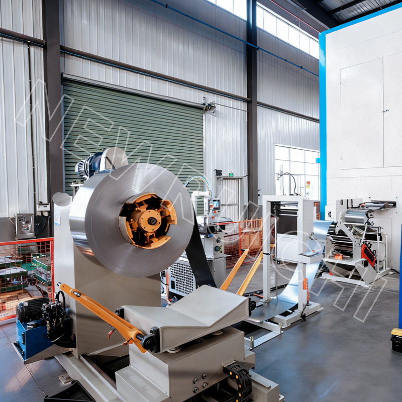 High-Grade Non-Grain-Oriented Silicon Steel CoilsNGO silicon steel coils with low core loss and uniform thickness for motor and transformer cores, available in custom widths and surface treatments.View Product →
Maintenance and Compliance Points That Get Missed
Single-phase motors carry wear items that three-phase motors do not. Run capacitors lose capacitance gradually, which raises current and temperature long before the motor fails outright; in hot enclosures, plan on inspection every three to five years and replacement when capacitance drops more than 10 percent below rated. Centrifugal switches and start relays arc every start, so contact condition belongs on the preventive maintenance list.
Three-phase motors trade those items for supply sensitivity. Voltage imbalance above about 1 percent causes a disproportionate current imbalance and rapid winding heating, so phase-failure and imbalance protection is not optional on unattended sites. Where a VFD is used, specify insulated bearing end closures and check that the winding insulation system is rated for the inverter's dv/dt, especially on long cable runs.
On the compliance side, efficiency regulations and IE classes generally target three-phase machines, which means single-phase units can quietly sit outside the framework. If a tender requires an efficiency class, confirm in writing which motor types the regulation actually covers before you accept a declaration on a single-phase unit.
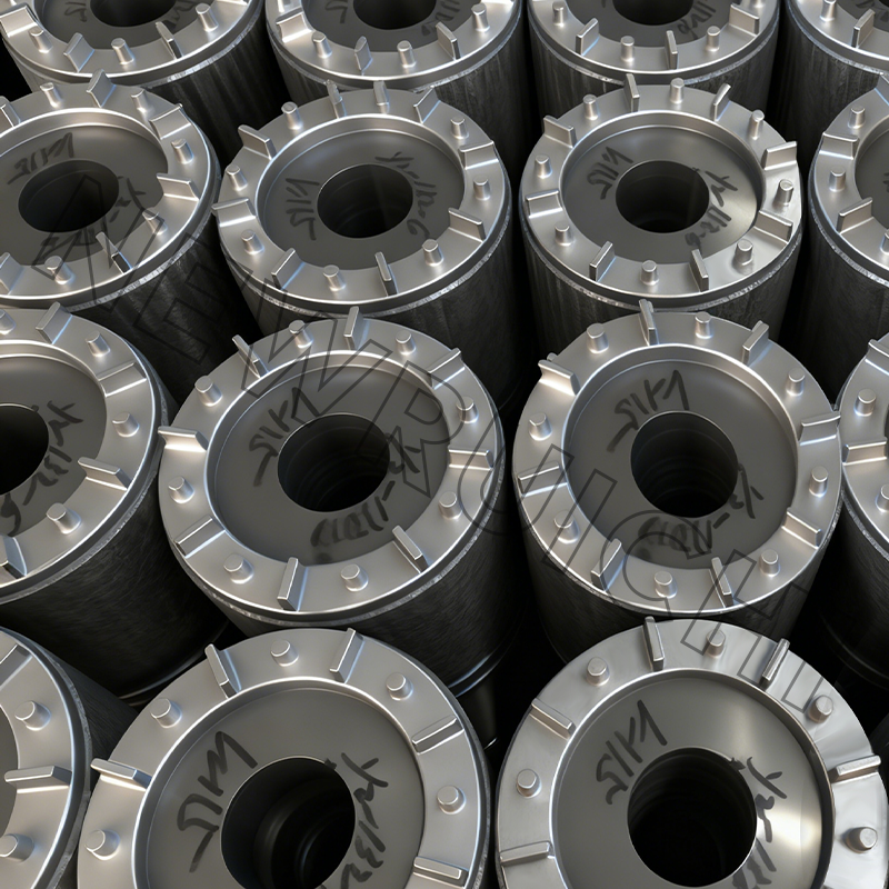 Interlock Laminated Motor Core AssemblyWeld-free, glue-free interlocked laminated cores for motors and transformers, offering consistent magnetic paths and stable mass-production quality.View Product →
Whichever type you buy, the stator and rotor core is where losses are decided before the winding is ever inserted. Consistent lamination quality, controlled stacking pressure, and a stable steel supply chain matter more to long-term performance than a marginal difference in catalogue price, and they are the part of the specification worth auditing on the supplier's floor rather than on the datasheet.
Your email address will not be published. Required fields are marked *


 Email: [email protected]
[email protected]
 Telephone/Phone:
+86-18861576796 +86-18261588866
+86-15305731515 +86-18861576796
Copyright © Wuxi New Ruichi Technology Co., Ltd. / Wuxi Cailiang Machinery Co., Ltd. All rights reserved.
Stator And Rotor Cores Manufacturers
