 en
 русский
 Deutsch

Electric Motor Reliability: Failure Rates, Core Quality, and Maintenance Trade-offs
A 250 kW pump motor that trips during a peak-load shift rarely fails for one dramatic reason. More often, the root cause is a stack of small tolerances: a hot bearing, a loose mounting foot, a contaminated winding, or a laminated core that was never quite right. Plant teams feel the downtime first; the reliability answer usually sits upstream in design, component quality, and installation discipline.
The short answer: electric motors are inherently reliable when specified, installed, and maintained within their electrical, thermal, and mechanical limits. Large-motor reliability studies commonly land around 3.4% failures per motor per year, and the spread between a good and poor installation is often wider than the spread between motor brands. Core quality sets the efficiency and thermal ceiling; bearings, alignment, cooling, and voltage quality decide how long the motor stays there.
Content
Reliability Is a System Property, Not a Motor Spec
A motor datasheet can promise insulation class, efficiency, and temperature rise, but reliability is a system property. It depends on how the stator and rotor core behave under magnetic stress, how the frame handles vibration, how the bearing housing holds alignment, and how the driven equipment loads the shaft. In practical terms, four levers dominate:
Magnetic core quality
Lamination grade, burr height, insulation coating, stacking pressure, and interlock or weld quality affect core loss, noise, and hot spots.
Mechanical fit
Concentricity, end-frame machining, bearing fits, and mounting flatness decide vibration and bearing life more than catalog efficiency.
Thermal path
Fan design, frame cooling, ambient temperature, and duty cycle interact. A 10°C rise above design limits can shorten insulation life substantially.
Electrical supply
Voltage imbalance, harmonics, and repeated starts stress windings and cores. Reliability testing should include the supply, not only the motor.
This is why two motors with the same nameplate rating can behave differently. One may run cool and quiet for a decade; another may develop bearing noise in 18 months because the core stack, frame weld, or shaft alignment introduced a vibration path that nobody checked at commissioning.
Core Quality and Failure Patterns Buyers Can Actually Verify
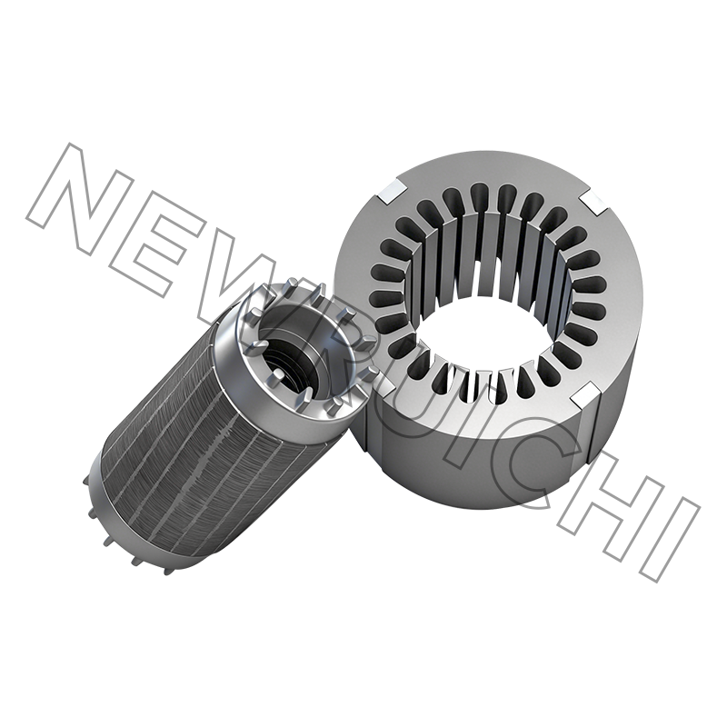
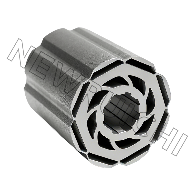
Stator and rotor laminations are not commodities once a motor moves into higher efficiency, higher speed, or higher duty. Burr height, coating thickness, stacking pressure, and interlock geometry influence core loss, tooth stiffness, and heat concentration. A poorly stacked core can pass a no-load test and still create local hot spots under load. Buyers should ask for lamination material grade, burr control, stacking force, and insulation resistance between laminations, then connect those checks to the manufacturing chain that will produce the finished core.
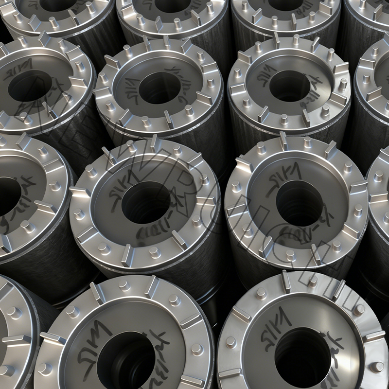 Interlock Laminated Motor Cores for Consistent Magnetic PathsA weld-free, glue-free finished core with precisely aligned laminations, suited to buyers evaluating stacking quality and magnetic-path consistency in higher-duty motors.View Product →
For medium and large motors, the failure pattern is usually less mysterious than the root cause. Bearing issues dominate, followed by stator winding faults, rotor problems, and coupling or alignment errors. Environmental contamination and poor cooling turn small defects into repeat failures. The table below is a practical triage view, not a universal ranking.
Where downtime actually accumulates
The practical takeaway is not to chase every failure mode equally. Start with bearing protection and alignment, then verify winding cleanliness and cooling, then audit core quality for motors that run hot, noisy, or current-imbalanced. For teams moving toward ready-to-install components, finished core assemblies can reduce stacking variation and incoming inspection burden, but only when the supplier controls lamination burr and stack pressure consistently.
Application Priorities: Reliability Looks Different by Duty Cycle
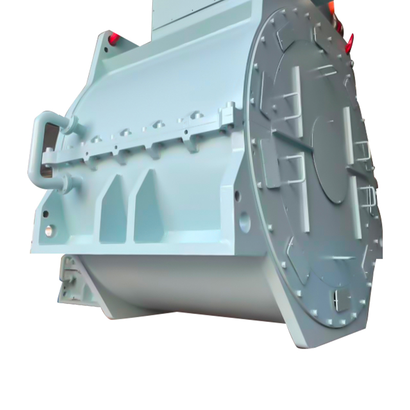
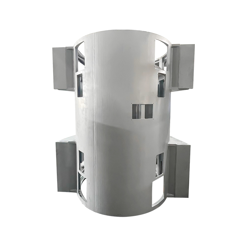
A wind-turbine generator base, a marine water-cooled motor mount, and an EV traction core do not face the same reliability stress. Wind equipment prioritizes structural fatigue life and corrosion protection; marine equipment adds salt spray, shaft clamping, and cooling reliability; high-voltage industrial motors weigh thermal margin and partial discharge risk; EV traction cores emphasize lamination precision, adhesive or interlock consistency, and high-volume repeatability. The chart below is a practical planning view of where motor reliability attention is concentrated across common industrial applications.
25% wind turbine and generator structures
25% high-voltage industrial motors
20% marine motors and generators
15% new energy vehicle traction
15% servo, stepper, and robotics
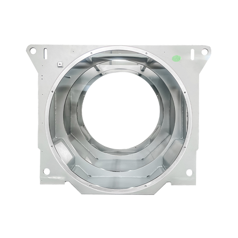
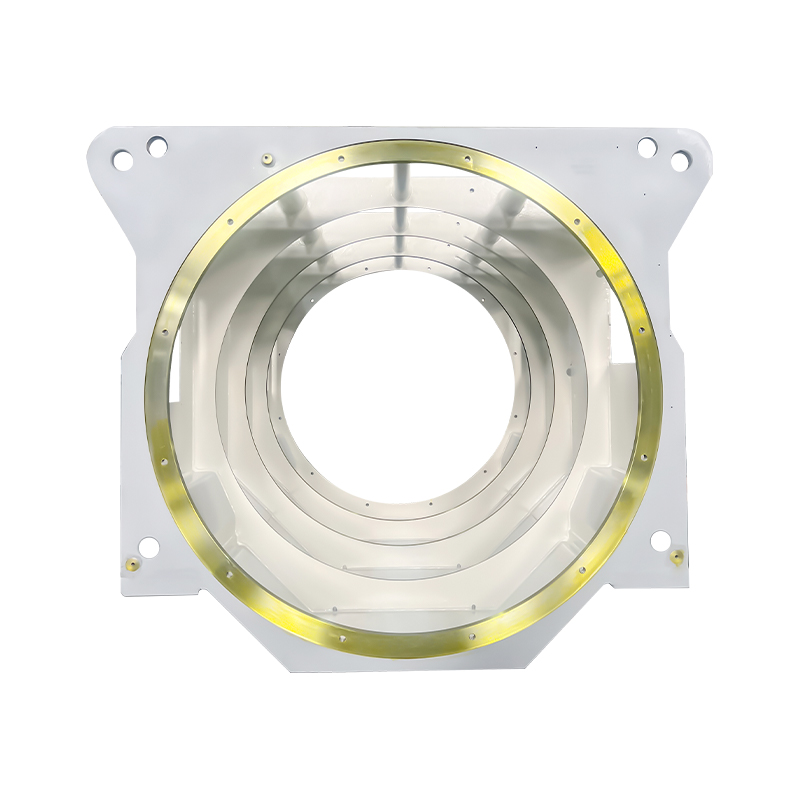
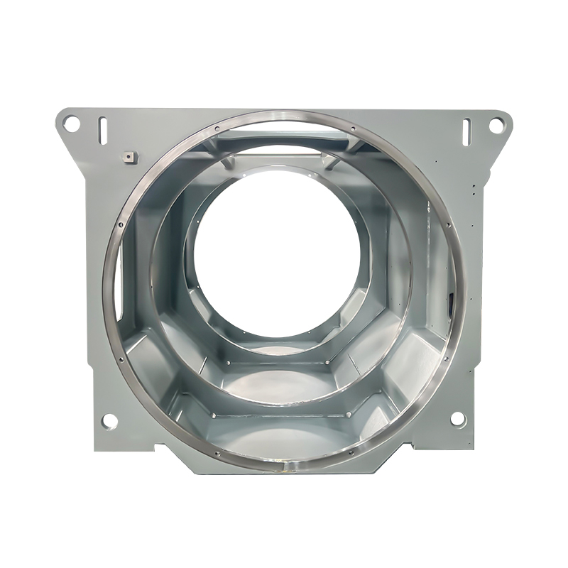
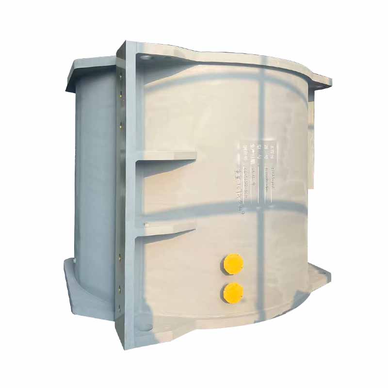
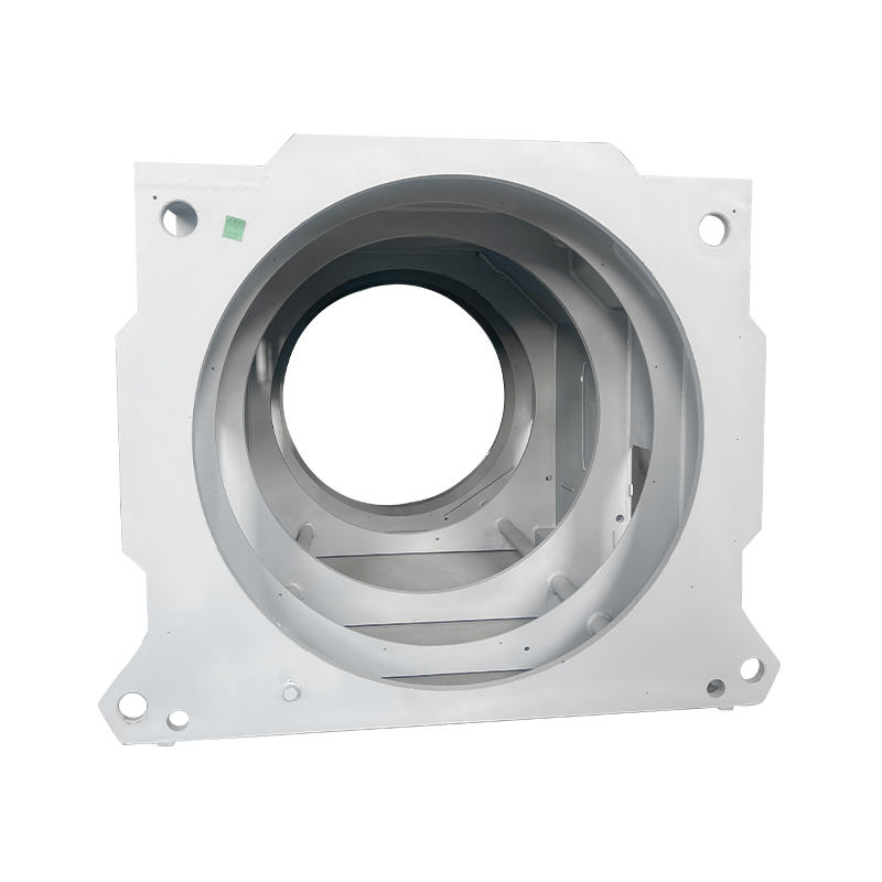 Industrial Welded Box-Type Motor Base for Heavy-Duty FramesSteel-plate welded enclosure with stiffeners, leveling feet, cooling passages, and maintenance access, relevant when frame rigidity and bearing alignment matter.View Product →
For wind and heavy industrial duty, the frame and base are reliability parts, not just mounting hardware. Weld quality, rib placement, and machining flatness affect vibration transmission and bearing alignment. A welded box-type base with controlled weld procedure and dimensional verification is often more valuable than a slightly higher motor efficiency rating.
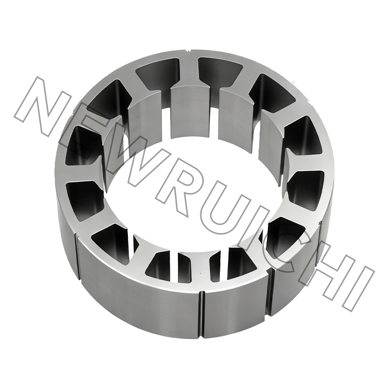
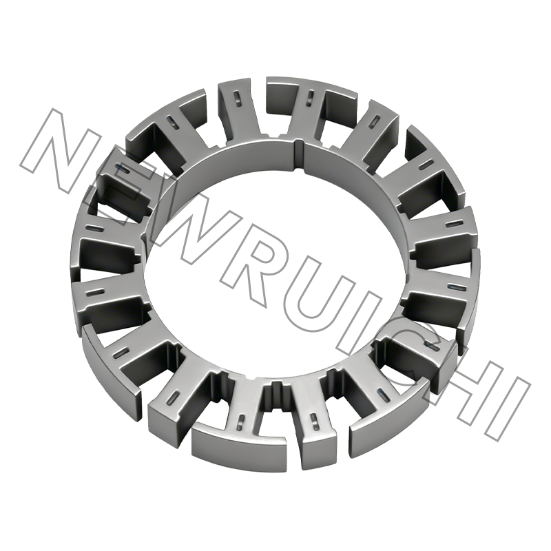
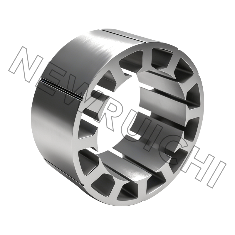
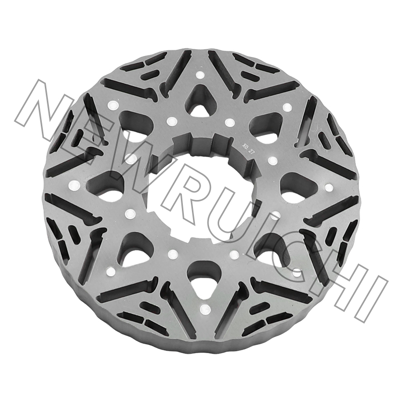
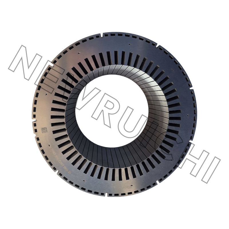 New Energy Vehicle Motor Stator and Rotor Core AssemblyHigh-precision laminated stator and rotor assembly using stacking, riveting, welding, or bonding, positioned for NEV drive motors needing stable magnetic paths and repeatable performance.View Product →
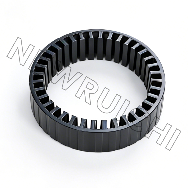
For EV traction and servo applications, the core assembly becomes the repeatability lever. Interlock, adhesive-bonded, or laser/TIG-welded cores each trade off mechanical stiffness, eddy-current loss, and production speed. The right choice depends on speed range, vibration profile, and whether the motor will be produced in sample quantities or high-volume batches.
A Practical Selection and ROI Workflow
Reliability improvements pay back through avoided downtime, longer service intervals, and lower rework. Use a short workflow before committing to a motor or core supplier:
1. Define duty cycle
Record starts per hour, load profile, ambient temperature, altitude, and expected service life. A motor selected for continuous duty can fail early in cyclic duty.
2. Check thermal margin
Verify cooling method, fan coverage, and enclosure against actual contamination. A 10°C margin is cheaper than a premature rewind.
3. Audit core and frame
Ask for lamination grade, burr limit, stacking pressure, interlock pattern, weld qualification, and frame machining reports.
4. Validate first article
Run no-load and load tests, check vibration, temperature rise, current balance, and insulation resistance before full release.
ROI is usually clearer when you calculate downtime, not just energy. A 250 kW motor running 6,000 hours per year consumes 1.5 million kWh. A 1% efficiency gain saves about 15,000 kWh per year; at $0.10/kWh, that is $1,500. One avoided 8-hour outage at $5,000 per hour is $40,000. That is why reliability specifications should focus on bearing protection, thermal margin, and core consistency before chasing small nameplate gains.
Maintenance and Compliance: Keep the Reliability You Paid For
Installation quality and maintenance discipline protect the reliability built into the motor. A practical schedule should include:
- Vibration checks at commissioning and after any coupling or base work.
- Laser alignment and soft-foot verification before the first long run.
- Lubrication records matched to bearing type, speed, and ambient conditions.
- Winding insulation resistance and polarization index trends, not one-off readings.
- Cooling-path cleaning and fan inspection, especially in dusty or marine environments.
- Voltage imbalance and harmonic checks after any drive or upstream electrical change.
Supplier compliance is part of reliability, too. ISO 9001 covers general quality management; IATF 16949 matters for automotive and EV core supply; ISO 3834 is relevant when motor frames and bases are welded structures; ISO 14001 indicates environmental process control. These certificates do not guarantee a low-vibration motor, but they do indicate whether the supplier has a traceable process for lamination burr, stacking pressure, weld parameters, and inspection records. For electric motor reliability, the best specification is one that connects the core, frame, installation, and maintenance evidence into a single review.
Your email address will not be published. Required fields are marked *


 Email: [email protected]
[email protected]
 Telephone/Phone:
+86-18861576796 +86-18261588866
+86-15305731515 +86-18861576796
Copyright © Wuxi New Ruichi Technology Co., Ltd. / Wuxi Cailiang Machinery Co., Ltd. All rights reserved.
Stator And Rotor Cores Manufacturers
