 en
 русский
 Deutsch

Armature DC Motor Guide: Laminations, Windings, and Core Assembly Choices
A converter line runs three 24 V permanent-magnet DC gearmotors at 1,800 rpm. At roughly 4,500 operating hours, one unit starts sparking visibly at the brush boxes and loses about 6% of its speed under the same load. The windings test clean. The fault sits in the armature: a grooved commutator, a rotor stack running a few hundredths of a millimetre eccentric since a rebuild, and brushes bedding on barely 60% of their face.
The conclusion first: the armature is the rotating winding assembly that carries current, cuts the field flux and produces torque. The commutator and brushes are what keep that current flowing in the right direction as the rotor turns. In a DC machine these parts are judged together, not one at a time. A lamination stack held to tight burr and concentricity limits is worth little if the commutator is out of round, and a perfect commutator cannot rescue a stack full of interlaminar shorts.
What follows is a practical view of the armature side of a DC motor: the magnetic circuit, the winding, the commutation limit, and how the core is actually bought, from sample laminations to series delivery.
Content
- 1 How the Armature Produces Torque, and Where Commutation Bites
- 2 Armature Voltage or Field Control: Decide Before You Buy
- 3 Three Ways to Build the Rotor Stack, and What Each One Costs
- 4 Losses You Will Not Find on the Datasheet
- 5 Where Brushed DC Armatures Still Win
- 6 Buying the Core: Tolerances, Tests and the Risks You Carry
- 7 From Sample to Series: A Sequence That Holds
- 8 Maintenance and Compliance Notes
How the Armature Produces Torque, and Where Commutation Bites
Two relationships explain most bench measurements on a brushed DC motor, and both point straight back to the armature.
- Torque: T ≈ k · Φ · Ia, field flux multiplied by armature current.
- Back EMF: E ≈ k · Φ · ω, which rises with speed and sets the running current at a given supply voltage.
- Current path: supply, brush, commutator segment, armature coil, return brush.
- Commutation: the commutator reverses coil current as each coil crosses the magnetic neutral, so coil current alternates even though the supply is DC.
- Armature reaction: the armature's own magnetomotive force tilts and weakens the main field and shifts the neutral axis. At high current it appears as sparking on the trailing brush edge and a small loss of torque per ampere.
Magnetic circuit
Rotor and stator laminations are stacked from non-oriented electrical steel, normally 0.35 mm or 0.50 mm. Thinner gauge trims eddy-current loss but lowers stacking factor and raises cost per kilogram, so it is rarely a free improvement.
Winding
Copper fill, wire gauge and end-turn length set the I²R loss. Insulation class F or H sets how much thermal margin you are allowed to use before the winding is the limiting part.
Commutation
Brush grade, spring pressure, commutator eccentricity and undercut depth decide sparking. Runout beyond roughly 0.02 mm usually shows up as brush noise long before it shows up as a failure, which is why the fault above was traceable at 4,500 hours rather than at 500.
Armature Voltage or Field Control: Decide Before You Buy
Speed range is a control decision, but it constrains the armature design. Armature voltage control, used below base speed, delivers roughly constant torque and wide turndown — the usual choice for conveyors, feed rolls and positioning axes. Field weakening, used above base speed, delivers roughly constant power, but commutation margin falls as flux drops and the field supply has to stay stable under load.
PWM drives at 20 kHz and above keep current ripple, and the extra armature heating that comes with it, small; below that, check brush and core losses at the actual carrier frequency rather than assuming the datasheet number holds. Series-wound motors cannot be field-weakened the same way, because field and armature share the same current. Use series-rated drives or resistance control, and accept that the speed regulation will be softer.
Three Ways to Build the Rotor Stack, and What Each One Costs
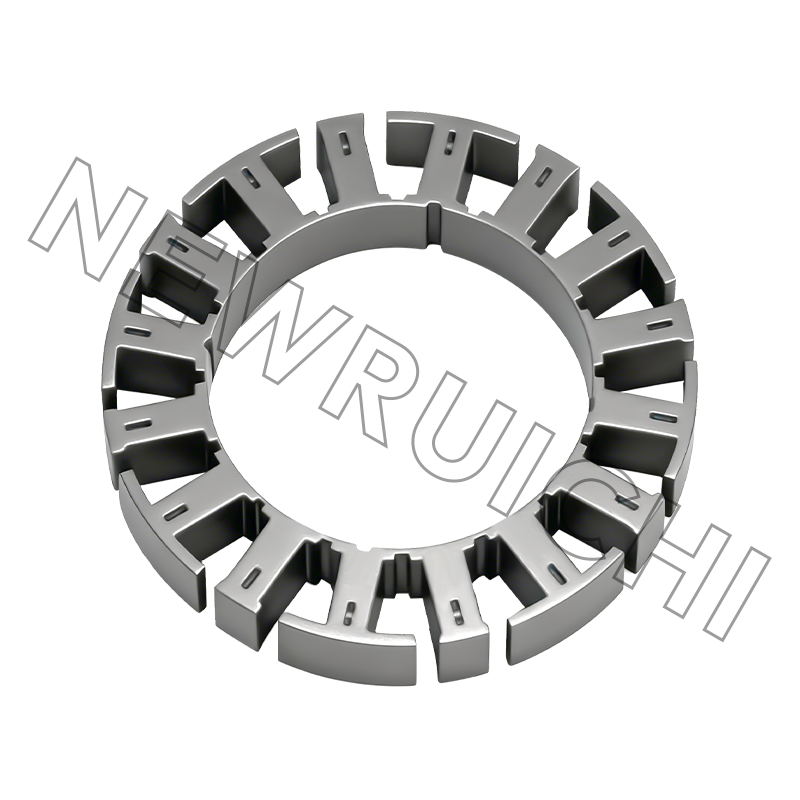
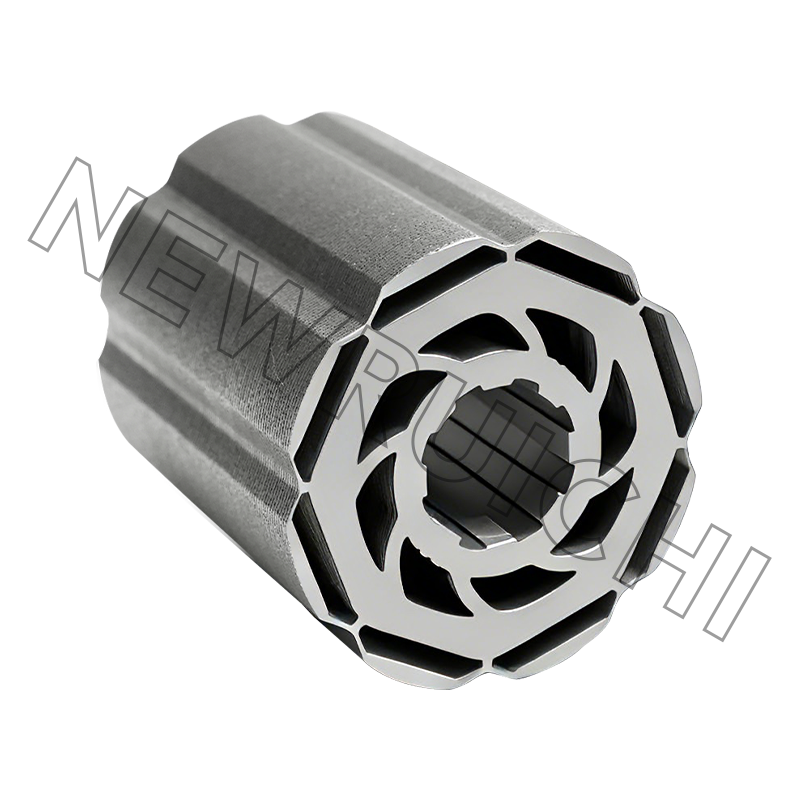
The trade-off is not abstract. An interlocked stack saves tooling money, but the notches create local saturation and metal-to-metal contact. An adhesive-bonded stack keeps the insulation coating intact and usually measures the lowest core loss, at the price of fixtures and cure time. Welded stacks sit in between and are chosen when the mechanical integrity of a long stack matters more than a couple of watts. Where interlock geometry is the deciding factor, the behaviour of interlocked laminated cores in precision assemblies is worth reviewing before the drawing is frozen.
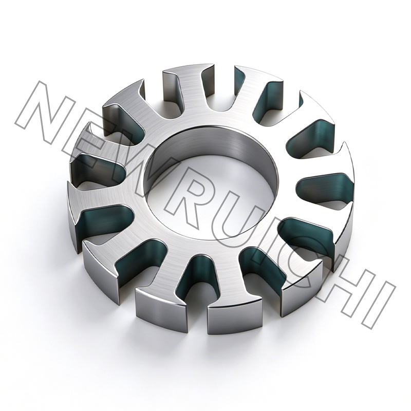
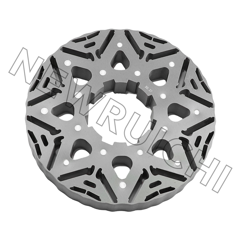
If the design is still open, buying rotor and stator laminations to drawing is the fastest way to compare stack builds before committing to a die.
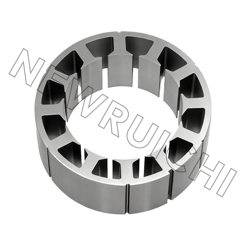
 DC Motor Stator and Rotor LaminationsCustom stator and rotor laminations support design-stage stack comparisons before tooling commitment, helping evaluate magnetic loss and assembly fit.View Product →
Losses You Will Not Find on the Datasheet
A datasheet gives one efficiency figure at one operating point. The split between loss mechanisms is what decides whether the armature runs warm at half load or overheats at 80% of rating.
Indicative split in a small brushed DC motor at rated load; actual shares shift with flux density, speed and brush grade.
Copper loss scales with the square of current, so a 10% overload adds roughly 21% more heat in the winding. That is why brush and winding failures rarely occur at the current printed on the label. Core loss is fixed by flux density, steel gauge and the number of interlaminar shorts, which means a stack with scratched coating heats up even at no load — a useful diagnostic when an assembled motor idles hot.
Where Brushed DC Armatures Still Win
Brushed DC is not legacy everywhere. It holds on where a two-wire connection, high starting torque and a low-cost drive outweigh periodic brush maintenance.
Indicative split of typical brushed DC armature demand, not a market study.
Each segment stresses the armature differently. Automotive auxiliaries punish thermal cycling and vibration, medical and mobility units punish acoustic noise and commutator film stability, and power tools punish peak current. A stack that suits one rarely suits all three without changes to steel grade or build method.
Buying the Core: Tolerances, Tests and the Risks You Carry
| Characteristic | Typical requirement | Why it matters |
|---|---|---|
| Lamination burr height | 0.05 mm or less; 0.03 mm on tight stacks | Burrs short adjacent laminations and raise core loss |
| Rotor OD and shaft bore | Per drawing, commonly ±0.05 mm | Sets air gap and shaft fit; eccentricity shows up as vibration |
| Stack length | Typically ±0.2 mm | Changes flux and torque constant from unit to unit |
| Stacking factor | 0.95 to 0.98 depending on build | A lower factor means more copper for the same torque |
| Interlaminar insulation | No visible coating damage | Scratched coating creates shorts and local hot spots |
| Skew angle | Per drawing, usually one slot pitch | Incorrect skew raises cogging torque and audible noise |
| Commutator runout after assembly | 0.02 mm or better | Directly controls sparking and brush life |
Where purchase risk actually accumulates is upstream of the drawing. Five failures account for most of the disputes we see:
- Steel grade substituted for a cheaper non-oriented grade with higher loss.
- Weld spatter or restruck interlocks that flatten the stack and short the laminations.
- Coating damage from bulk handling before the stack is bonded.
- Material supplied unannealed, which lifts core loss without changing a single dimension.
- Lots mixed inside one stack, showing up as unit-to-unit scatter in current draw.
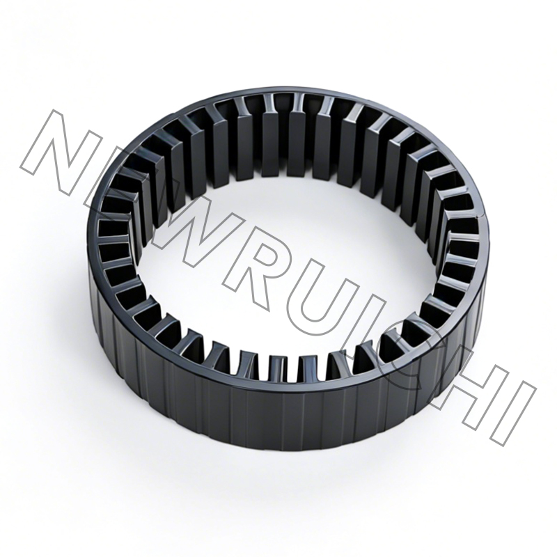
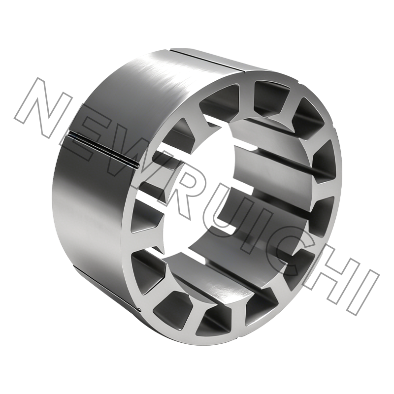
For volume programmes, buying a finished stack rather than loose sheets moves those risks to the supplier and removes the stack-length variation from your assembly line.
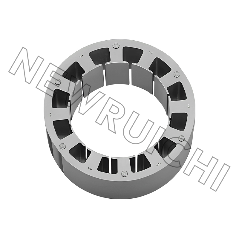 DC Motor Stator and Rotor Core AssembliesFinished laminated core assemblies suit volume motor programmes by shifting stacking risk to the supplier and reducing stack-length variation on the assembly line.View Product →
From Sample to Series: A Sequence That Holds
1. Drawing and steel review.
Confirm gauge, grade, coating weight and stack build before any material is cut.
2. Laser-cut samples.
A few hundred pieces, no tooling, delivered while the design is still moving.
3. Stack and bond trial.
Measure achieved stacking factor and stack length against the drawing.
4. Fit, spin and thermal test.
Air gap, runout, temperature rise at rated load, and brush behaviour at the commutator.
5. Volume tooling.
Stamping die or laser batch, whichever matches the quantity and the change risk.
6. First article and documentation.
Dimensional report, material certificates, and PPAP where the programme is automotive.
Samples cut by laser also let you test a steel grade change before committing to a die. A 0.35 mm grade that measures lower core loss may or may not justify the extra cost per kilogram, and a stack trial answers that question in a week rather than a quarter.
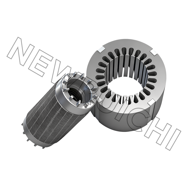
 Laser-Cut Stator and Rotor Lamination SamplesCustom laser-cut lamination samples support early motor design checks and steel-grade trials before die commitment and volume production.View Product →
Past the sample stage, the lamination and core manufacturing route — steel slitting, stamping or laser cutting, annealing where specified, stacking by interlock, adhesive or weld, and final inspection — is where delivery dates are won or lost. It is worth walking that flow once with the supplier before the first purchase order, not after.
Maintenance and Compliance Notes
- Inspect brushes at half the expected wear life, not at failure.
- A uniform chocolate-coloured commutator film is healthy; patchy film points to contamination or the wrong brush grade.
- Keep spring pressure in specification. Low pressure glazes the commutator, high pressure wears brushes quickly.
- Clean with a solvent compatible with the winding insulation; carbon dust conducts.
- Store stacked cores dry and wrapped, because interlaminar rust behaves exactly like an electrical short.
On the compliance side, motor cores for automotive programmes generally sit inside an IATF 16949 quality system, general industrial cores under ISO 9001, and welded frames and bases under ISO 3834, with environmental management following ISO 14001. Those certificates matter less as paper and more as the reason first-article reports, material certificates and change notifications arrive without being chased.
None of this makes the armature complicated. It makes it specific: steel grade, stack build, burr limit, commutator runout. Settle those four and the 4,500-hour sparking problem stops being a mystery.
Your email address will not be published. Required fields are marked *


 Email: [email protected]
[email protected]
 Telephone/Phone:
+86-18861576796 +86-18261588866
+86-15305731515 +86-18861576796
Copyright © Wuxi New Ruichi Technology Co., Ltd. / Wuxi Cailiang Machinery Co., Ltd. All rights reserved.
Stator And Rotor Cores Manufacturers
