 en
 русский
 Deutsch

A Consequent Pole Motor Has Two Speeds: Winding Types, Core Design, Selection
Two 22 kW fan motors, same frame size, same manufacturer, same duty cycle: one nameplate reads 1,800 rpm, the other reads 1,800/900 rpm. The second is a single-winding consequent pole machine, and every difference between the two sits inside the stator lamination stack and the terminal box.
When someone asks what a consequent pole motor has, the answer starts with two speeds from one winding, roughly half the coil groups of a comparable conventional winding, and a set of unwound poles that carry flux without carrying copper. The less comfortable half of the answer is a flattened air-gap flux waveform, more harmonic loss in the core, and less cooling at the low speed. Those three items are decided as much by the lamination supplier as by the motor designer.
Content
- 1 The Short Answer, in Plain Numbers
- 2 How One Winding Produces Two Pole Numbers
- 3 Consequent Pole Versus Conventional Winding
- 4 The Metrics That Only Appear After the First Prototype
- 5 Where Consequent Pole Machines Actually Run
- 6 The Second Meaning: Consequent Pole Permanent Magnet Rotors
- 7 Specifying Cores for a Two-Speed Machine: A Workable Sequence
- 8 Maintenance and Compliance Details That Get Overlooked
The Short Answer, in Plain Numbers
A consequent pole motor has the following characteristics, and each one has a direct consequence for the stator and rotor cores a buyer has to specify.
- Two speeds from one winding. The usual ratio is 2:1, so 1,800/900 rpm at 60 Hz and 1,500/750 rpm at 50 Hz.
- Six coil groups instead of twelve in a three-phase, four-pole frame.
- Unwound poles. Only half the poles carry coils, and the remaining poles take their polarity from the iron path, which is where the term consequent comes from.
- Less copper and shorter end windings, because both coil group count and inter-group connections fall.
- A flattened flux waveform. The unwound poles present a different effective air-gap permeance, so harmonic content rises.
- A cooling penalty at low speed. A shaft-mounted fan at half speed moves far less than half the air it moves at full speed.
For a purchasing or engineering team specifying cores, the unwound poles and the flux waveform matter most. A consequent pole stator is not a standard four-pole stator with a different nameplate; its tooth and yoke sections are driven by the low-speed connection.
How One Winding Produces Two Pole Numbers
A conventional three-phase four-pole concentric winding needs twelve coil groups: four poles multiplied by three phases. A consequent pole winding in the same stator uses six. Each group is connected so that flux leaving a wound pole returns through a pole that carries no coil of its own. Because the unwound pole is fed by the same iron path, it takes the opposite polarity to its neighbours and works exactly like a wound pole of the opposite sign.
Connect that winding one way and the machine runs as four poles. Reconnect it and the same copper behaves as eight effective poles. Synchronous speed follows pole count, so a 60 Hz machine gives 1,800 rpm and 900 rpm. With slip, a loaded squirrel-cage motor typically settles near 1,750 rpm and 875 rpm.
Fewer coil groups
Six groups instead of twelve means less copper, shorter end turns, fewer joints and a shorter axial build. Winding tooling and coil insertion time both drop, which is why the design survives in cost-sensitive volume production.
Higher harmonic loss
The air-gap flux waveform is flatter in the consequent pole connection. Extra third and fifth harmonic content raises core loss and audible noise, which is exactly the regime where a higher-grade, low-loss non-oriented silicon steel repays its extra cost.
Cooling at half speed
A shaft-mounted fan loses airflow much faster than it loses speed. Torque at 900 rpm is often acceptable; temperature rise frequently is not, and that gap is usually found on the test bench rather than in the design review.
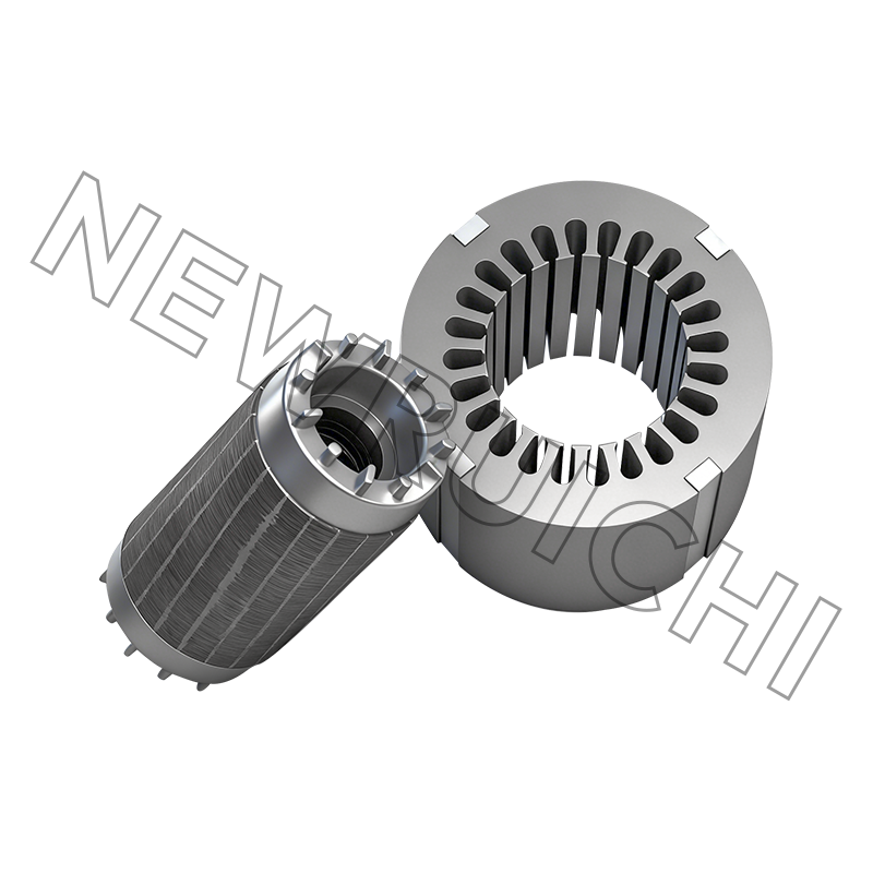
AC induction machines built on this principle rely on a stator and rotor core set that has already been dimensioned for both connections, which is the point at which component sourcing and motor design meet.
 AC Motor Stator and Rotor Core AssemblyHigh-precision stacked stator and rotor cores for AC motors, relevant when comparing conventional and consequent-pole arrangements in the same frame.View Product →
Consequent Pole Versus Conventional Winding
The comparison below is drawn for the same 60 Hz stator frame running either as a conventional four-pole single-speed motor or with a consequent pole single winding.
The Metrics That Only Appear After the First Prototype
Design reviews tend to focus on rated speed and torque. The chart below compares the same stator frame in the consequent pole connection against the conventional four-pole connection, indexed to 100 for the conventional case. These are typical prototype and test-bench observations rather than a single datasheet value, so treat them as ranges.
The two tall bars are the ones that generate redesign work. Vibration and noise rise because the unwound pole changes the force distribution around the air gap, and harmonic core loss rises because the flux waveform is no longer close to sinusoidal. Both effects push designers toward thinner laminations, lower-loss silicon steel grades, interlocked rather than welded stacks, and in many cases a skewed rotor. For a closer look at how stacking method shifts core loss, this comparison of interlock laminated cores covers the practical trade-offs.
Where Consequent Pole Machines Actually Run
Two-speed operation pays off wherever a load runs at full demand for part of the day and at part-load for the rest. The distribution below reflects the application mix seen in industrial fan, pump and compressor work.
The common thread is a square-law load. Fan and pump power falls roughly with the cube of speed, so a machine running at half speed needs about one-eighth of the shaft power at full speed. A consequent pole motor captures part of that saving with no drive electronics at all, which is why the design survives in cost-sensitive, high-duty applications even though variable frequency drives now cover most other cases.
The Second Meaning: Consequent Pole Permanent Magnet Rotors
The same term describes a completely different construction on the rotor side. In a consequent pole permanent magnet machine, magnets of a single polarity are mounted or embedded, and the iron poles between them are magnetized by the adjacent magnets to the opposite polarity. Half the poles are magnets, the other half are iron.
For a buyer, the consequences are both commercial and mechanical.
- Magnet mass falls substantially per pole pair, and magnets are the dominant cost item in traction, servo and appliance motors.
- The rotor becomes salient, so reluctance torque adds to magnet torque and the constant-power speed range widens, which helps in field-weakening operation.
- The flux path is asymmetric, which raises torque ripple, unbalanced magnetic pull and rotor harmonic loss.
- Rotor lamination geometry becomes critical: pole arcs, flux barriers and bridge thickness have to be tuned together.
That last point is a manufacturing issue, not only a simulation issue. Rotor stacks of this type are usually interlocked rather than welded, because welding short-circuits laminations along the stack and adds core loss exactly where harmonic loss is already high.
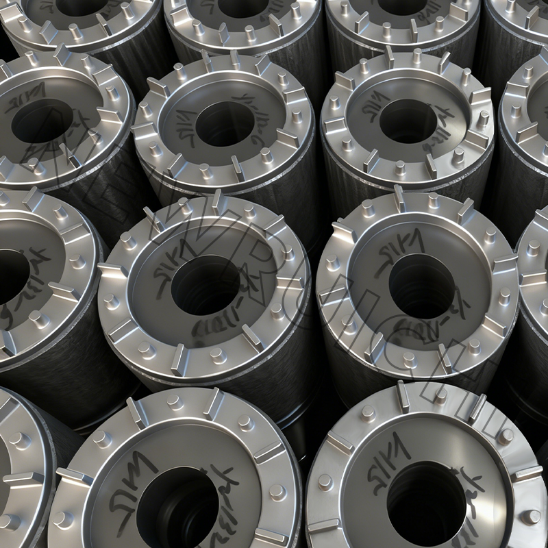 Interlock Laminated Core for Weld-Free Motor StacksFinished interlocked motor core assembly with weld-free, glue-free construction, relevant for two-speed rotor stacks where welding losses and manufacturing control are concerns.View Product →
Specifying Cores for a Two-Speed Machine: A Workable Sequence
- Fix the speed pair and the duty first. Confirm whether the low speed is continuous or used only for starting, positioning or night operation. A 2:1 ratio is standard, but other ratios are possible at the cost of winding complexity.
- Size the magnetic circuit for the worst flux condition. The unwound pole teeth and the yoke behind them carry concentrated flux, so check flux density in the low-speed connection rather than only at rated high speed.
- Re-check cooling at the low speed. If the fan is shaft-mounted, plan for forced ventilation, a larger fan, or a lower temperature-rise class. This decision often changes the frame and the housing.
- Choose the stacking method deliberately. Interlocking is fast and dimensionally stable in volume; adhesive bonding gives the lowest core loss; laser or TIG welding tools up quickly but creates inter-lamination short circuits that cost loss. Two-speed machines with high harmonic content feel that penalty more sharply than single-speed machines do.
- Validate with laser-cut samples before committing to hard tooling. Sample laminations let the team measure no-load current, temperature rise and noise on the real connection.
- Lock the documentation. Agree lamination thickness, silicon steel grade, stacking method, burr limits and inspection records before the first production order.
A supplier that controls both the silicon steel input and the finished stack removes one of the usual failure modes, which is a good reason to review the manufacturing chain before placing a two-speed core order.
Maintenance and Compliance Details That Get Overlooked
- Terminal identification. A consequent pole winding usually lands on six leads. Re-terminating a repaired motor on the wrong connection produces a machine that runs, but at the wrong speed and with excessive current.
- Contactors and switching. Speed change is done mechanically, not electronically. Pitted contacts and loose links are common reasons a motor refuses to reach the low speed.
- Temperature at the low speed. Verify it after any rewind. If a repair shop fits a generic shaft fan, the low-speed margin disappears.
- Insulation and temperature-rise limits. Check against IEC 60034-1 or NEMA MG 1, and confirm the insulation class the repair shop actually used rather than the class on the original nameplate.
- Material grade after a rebuild. In a two-speed machine, harmonic loss makes the silicon steel grade more influential than it is in a single-speed motor, so substituting a lower grade to save cost usually shows up as heat.
On the supply side, ask for documented quality systems rather than certificates in a brochure: ISO 9001 as a baseline, IATF 16949 where the motor ends up in a vehicle, ISO 14001 for environmental compliance, and ISO 3834 for welded frames such as box-type machine bases. Those documents are what keep a two-speed core order auditable from silicon steel coil to finished stack, including the raw material side such as high-grade non-oriented silicon steel in coil, strip or sheet form.
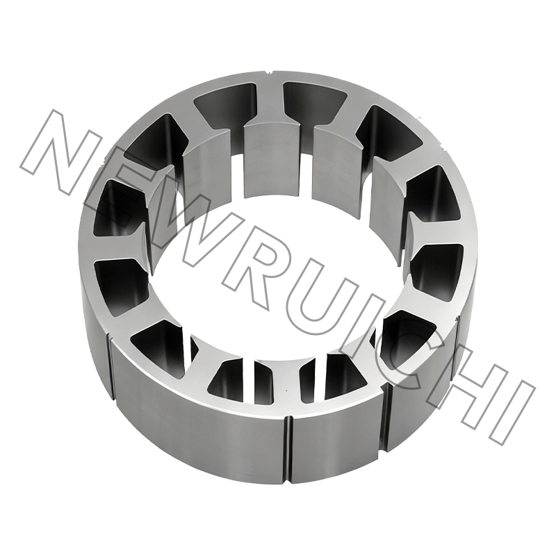
 Silicon Steel Roll, Strip, and SheetQuality-controlled silicon steel in roll, strip, and sheet forms for motor cores and precision stamping, relevant when specifying lamination material and supply documentation.View Product →
A consequent pole motor has two speeds from one winding, six coil groups instead of twelve, unwound poles that carry flux but no copper, and a flux waveform that is harder on the core than a conventional winding. Those facts turn into cost and risk at the lamination stage, because steel grade, lamination thickness, stacking method and stack length all have to be chosen for the low-speed connection and not only for the nameplate speed.
Your email address will not be published. Required fields are marked *


 Email: [email protected]
[email protected]
 Telephone/Phone:
+86-18861576796 +86-18261588866
+86-15305731515 +86-18861576796
Copyright © Wuxi New Ruichi Technology Co., Ltd. / Wuxi Cailiang Machinery Co., Ltd. All rights reserved.
Stator And Rotor Cores Manufacturers
