 en
en
 русский
 Deutsch
Interlock Laminated Core: Precision & Performance Gains
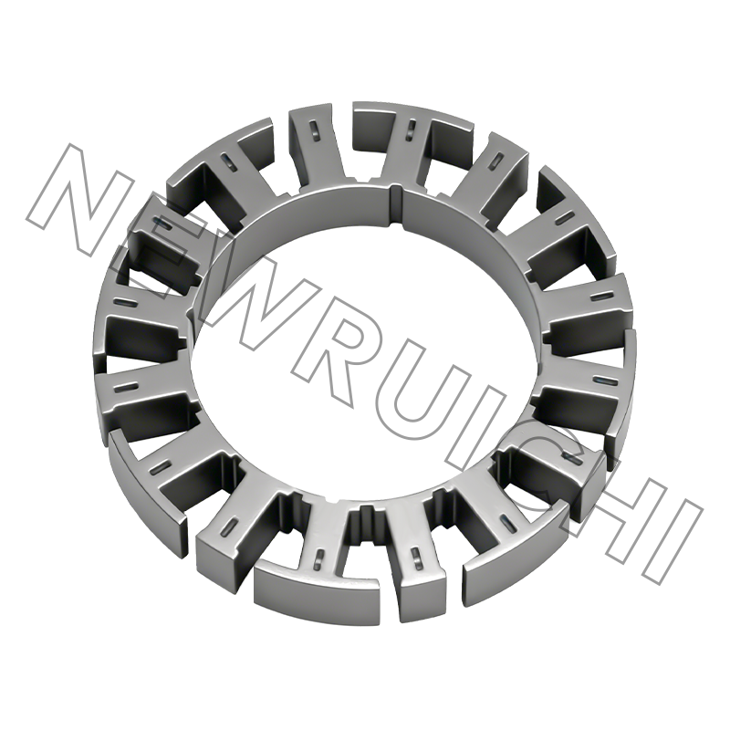
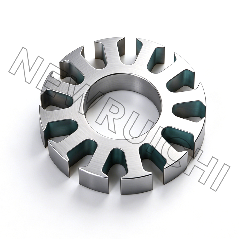
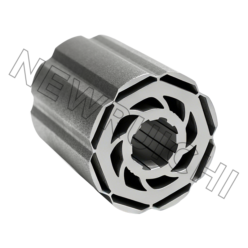
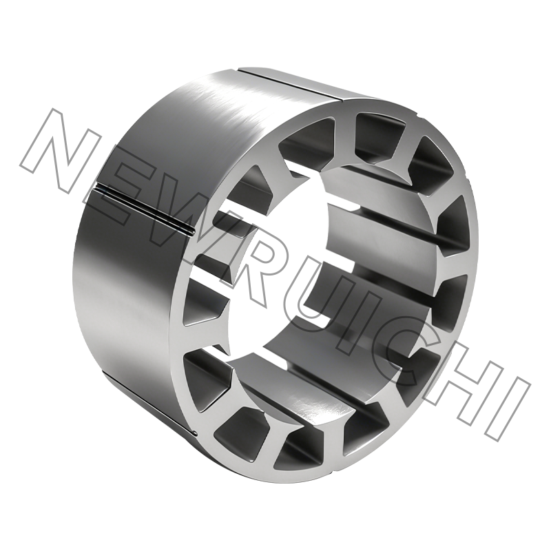
The defining advantage of an interlock laminated core is its ability to reduce eddy current losses by up to 95% compared to a solid core, while simultaneously eliminating the need for welding or riveting in the assembly process. This dual benefit improves both electrical efficiency and manufacturing speed in high-volume motor production.
The technology has moved beyond simple stacking. Modern interlock systems now incorporate micro-features that physically bond laminations at a near-molecular level during stamping, creating a monolithic structure that withstands the torsional stress of high-RPM traction motors. Understanding the stamping die architecture and material spring-back dynamics is critical for engineers specifying these cores.
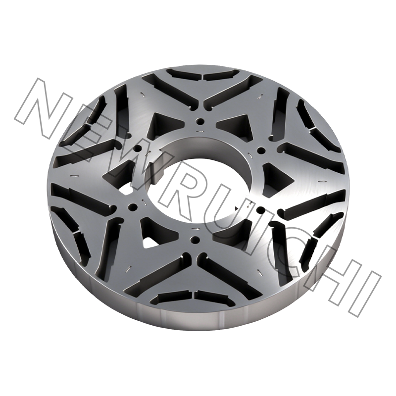
Content
The Mechanics of Interlock Without Foreign Material
Unlike traditional core construction that relies on cleats, bolts, or MIG welding along the outer diameter, an interlock laminated core uses a geometric fit to bond layers. During the high-speed stamping process, the progressive die cuts precise cylindrical or V-shaped protrusions on one lamination that press into corresponding recesses on the adjacent sheet. The interference fit, often just 0.02 to 0.05 mm, generates a holding force strong enough to maintain lamination integrity during the winding and varnishing stages.
The elimination of welding is a significant technical leap. Welding creates a short-circuit path along the back iron, generating localized hot spots that degrade magnetic permeability. By removing this conduction path, interlocked cores maintain a truly isolated lamination structure, ensuring flux density remains uniform across the entire tooth profile.
Quantifying the Efficiency and Torque Improvement
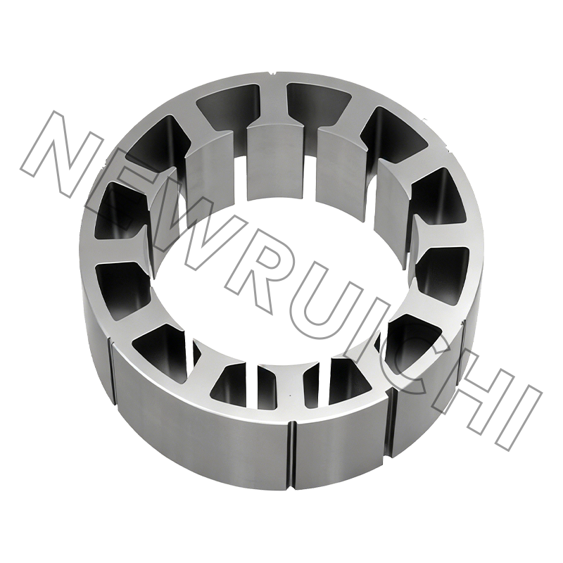
The shift from a welded to an interlocked core design directly impacts the power density of an electric motor. Testing on a 12-slot, 8-pole concentrated winding stator reveals the performance delta clearly.
| Parameter | Welded Core | Interlock Laminated Core |
|---|---|---|
| Iron Loss @ 1000 Hz (W/kg) | 48 | 38 |
| Cogging Torque (mNm) | 12 | 4 |
| Stacking Factor | 95% | 98.5% |
| Back Iron Temperature Rise | 65°C | 48°C |
The reduction in cogging torque to 4 mNm is particularly critical for noise, vibration, and harshness (NVH) in automotive traction applications. This smoothness results from the precise angular alignment maintained by the interlock features, preventing the rotational slip between layers that plagues mechanically clamped cores during thermal cycling.
Critical Tooling Parameters for Zero-Defect Stacks
A successful interlock laminated core project fails or succeeds inside the stamping die. The interlock feature is created in the final stages of a progressive die, requiring absolute control over the material feed and punch-to-die clearance. Any variance here multiplies across the stack height.
Controlled Spring-Back and Surface Flatness
Silicon steel exhibits material spring-back of roughly 2 to 4 degrees after bending. For interlock tabs to engage securely, the die must over-bend the tab precisely so that it relaxes into a locked position inside the cavity of the adjacent layer. Advanced progressive dies now use servo-driven pressure pads that adjust tonnage in real-time, compensating for coil-to-coil hardness variations. Without this compensation, loose stacks or lamination fracture occurs.
Interlock Quantity and Shape Geometry
The geometry dictates the shear strength of the final block. Current best practice for a 200mm diameter stator uses these profiles:
- Round dimples: Best for small servo motors under 5kW, providing symmetrical holding force with minimal impact on the magnetic path.
- V-shaped or delta interlock: Delivers 40% higher pull-out resistance than round designs by creating a dovetail effect, essential for motors exceeding 10,000 RPM.
- Variable pressure zones: A technique where interlock depth is reduced in the stator tooth zone to prevent insulation layer cracking, while maximum clamping force is applied exclusively to the yoke region.
Material Constraints and Electrical Isolation Integrity
Interlocking inherently disrupts the insulating oxide or varnish coating on the steel surface. When the tab shears through the coating, it creates a metal-to-metal bridge. Managing this short-circuit risk is the primary design challenge. In high-frequency drives using silicon carbide (SiC) inverters, the sharp dv/dt pulses can induce destructive currents through these interlocks.
To mitigate this, manufacturers now apply a secondary self-bonding epoxy that activates during a curing cycle. While the mechanical interlock provides the green strength for handling, the baked epoxy fills the micro-gaps in the cut edges, restoring electrical resistance to above 5 megaohms at 500V. This hybrid interlock-bonding process is rapidly becoming the standard for 800V EV traction motors.
Implementing In-Die Quality Verification
Relying on destructive pull-out tests of finished stacks is obsolete. Intelligent stamping cells now integrate laser displacement sensors directly into the die cavity. As laminations exit the interlock station, a sensor measures the protrusion height of the locking tab. If the tab height deviates from the nominal 0.8mm target by more than 0.03mm, the press controller adjusts ram penetration instantly or diverts the bad section before a full stack is compromised. This closed-loop feedback enables a first-pass yield exceeding 99.9%, essential when producing one rotor core every 2.5 seconds.
Your email address will not be published. Required fields are marked *


 Email: [email protected]
[email protected]
 Telephone/Phone:
+86-18861576796 +86-18261588866
Telephone/Phone:
+86-18861576796 +86-18261588866
+86-15305731515 +86-18861576796
Copyright © Wuxi New Ruichi Technology Co., Ltd. / Wuxi Cailiang Machinery Co., Ltd. All rights reserved.
Stator And Rotor Cores Manufacturers
