 en
en
 русский
 Deutsch
Wind Turbine Generator Housing & Frame Guide
Content
- 1 The Structural Role of the Wind Turbine Generator Housing
- 2 Load Conditions Acting on the Generator Frame
- 3 Design Differences: Geared vs. Direct-Drive Turbine Configurations
- 4 Materials and Manufacturing Methods for Generator Housings
- 5 Precision Alignment Requirements and Machining Standards
- 6 Surface Protection and Corrosion Prevention for Harsh Environments
- 7 Quality Assurance and Certification for Generator Frame Production
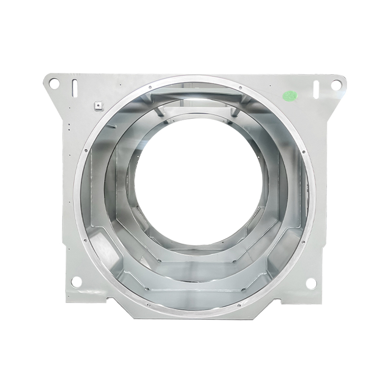
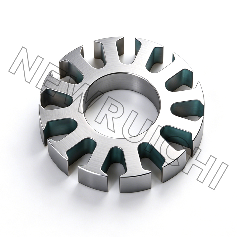
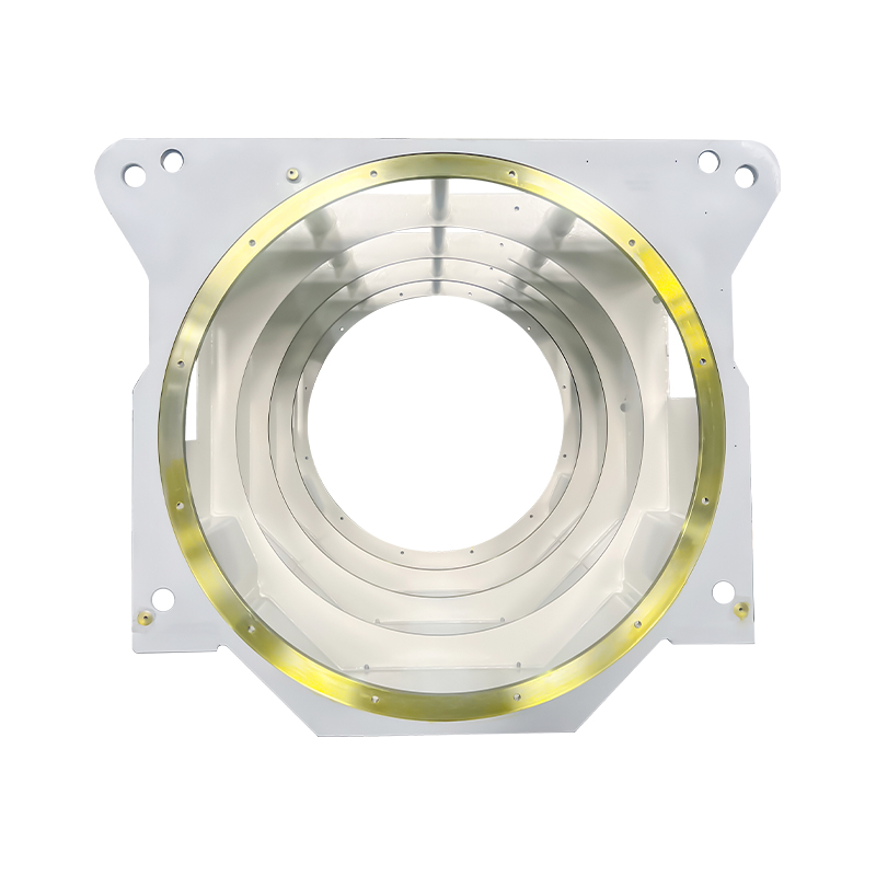
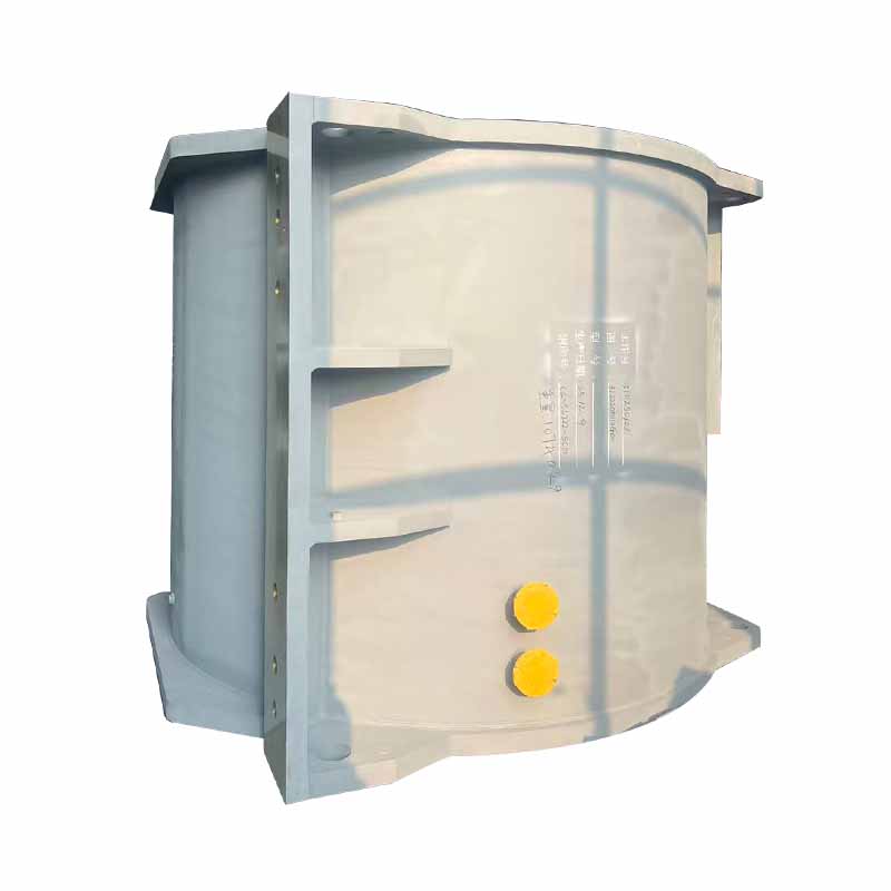
The Structural Role of the Wind Turbine Generator Housing
The wind turbine generator housing — also referred to as the wind turbine generator frame or generator base — is a critical core component of wind power generation units, positioned at the top of the tower inside the nacelle. Its function extends far beyond simple enclosure. The generator housing forms the primary load-bearing interface between the generator and the broader nacelle structure, connecting to the main frame at the front while supporting the full weight of the generator at the rear. In this position, it must simultaneously manage static gravitational loads, dynamic operational torque, wind-induced bending moments, and vibration transmitted through the drivetrain — all while maintaining the precise dimensional relationships required for efficient power generation.
The importance of the wind turbine generator frame is best understood by considering the consequences of its failure or dimensional inaccuracy. Misalignment between the generator and gearbox — or between the generator and main shaft in direct-drive configurations — introduces asymmetric bearing loads, accelerated gear and bearing wear, elevated vibration signatures, and ultimately premature drivetrain failure. Given that wind turbines are expected to operate for 20 to 25 years with minimal major maintenance, and that nacelle access at hub heights of 80 to 140 meters is logistically complex and costly, the structural integrity and dimensional precision of the generator housing are non-negotiable requirements with direct financial consequences across the turbine's operational lifetime.
Load Conditions Acting on the Generator Frame
The wind turbine generator frame operates in one of the most mechanically demanding environments in industrial equipment. Unlike stationary industrial machinery where loads are largely static and predictable, a wind turbine generator housing must withstand a continuous spectrum of dynamic loads whose magnitude and direction change constantly with wind conditions, turbine operating state, and yaw position. Understanding these load categories is essential for appreciating why generator frame design is a sophisticated structural engineering challenge rather than a straightforward fabrication task.
- Gravitational loads — The dead weight of the generator — typically 15 to 80 tonnes depending on turbine rating — acts as a constant downward force on the generator frame's mounting interface. In larger multi-megawatt turbines, this static load alone requires frame cross-sections and material specifications that would be considered overengineered in most industrial contexts.
- Operational torque — The reaction torque from generator electromagnetic braking — the force that resists rotor rotation as electrical power is extracted — is transmitted directly into the wind turbine generator housing. This torque can reach several hundred kilonewton-meters in multi-megawatt machines and reverses direction during grid fault events, imposing cyclic torsional stress on the frame structure throughout the turbine's operational life.
- Wind-induced bending moments — Thrust forces from the rotor create bending moments that propagate through the main shaft and gearbox into the generator frame. In extreme wind conditions — storm survival loads, emergency stop events — these moments reach their peak values and must be absorbed by the frame without permanent deformation that would compromise alignment.
- Vibration and fatigue loading — Rotor imbalance, blade passing frequency excitation, gear mesh harmonics, and generator electromagnetic torque ripple all generate vibratory loads at distinct frequencies. The wind turbine generator frame must be designed with sufficient stiffness to avoid resonance at these excitation frequencies and sufficient fatigue resistance to survive the billions of load cycles accumulated over a 20-year service life.
- Thermal loads — Temperature differentials between the generator housing interior — heated by generator losses — and the external nacelle environment create differential thermal expansion that must be accommodated without introducing misalignment or constraining the generator's thermal growth in ways that damage mounting interfaces.
Design Differences: Geared vs. Direct-Drive Turbine Configurations
The mechanical architecture of the wind turbine fundamentally shapes the design requirements for the wind turbine generator housing. Two dominant drivetrain configurations — geared and direct-drive — impose substantially different load profiles and alignment requirements on the generator frame, resulting in distinct structural designs optimized for each architecture.
Geared Turbine Generator Frames
In conventional geared wind turbines, the low-speed main shaft connects to a gearbox that increases rotational speed before driving a relatively compact high-speed generator. The wind turbine generator frame in this configuration must ensure precise alignment between the gearbox output shaft and the generator input shaft — typically achieved through a flexible coupling, but still requiring the two shaft centerlines to remain within tight angular and parallel misalignment limits under all operating load conditions. The frame's structural design must maintain this alignment despite the deflections caused by generator weight, torque reaction, and dynamic loads, requiring careful finite element analysis during the design phase to verify deflection compliance across the full load envelope.
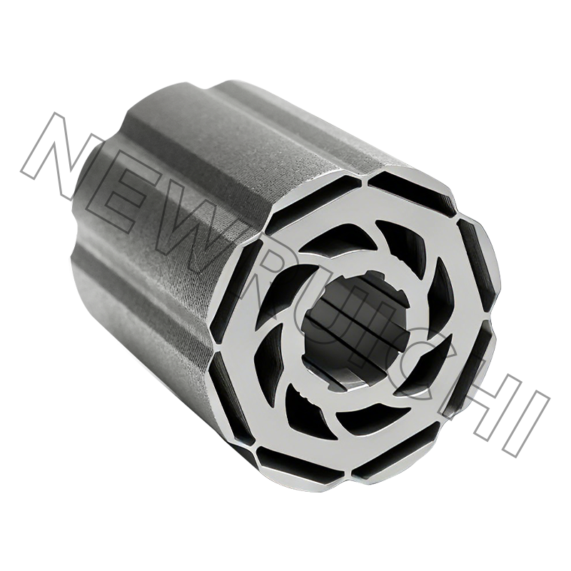
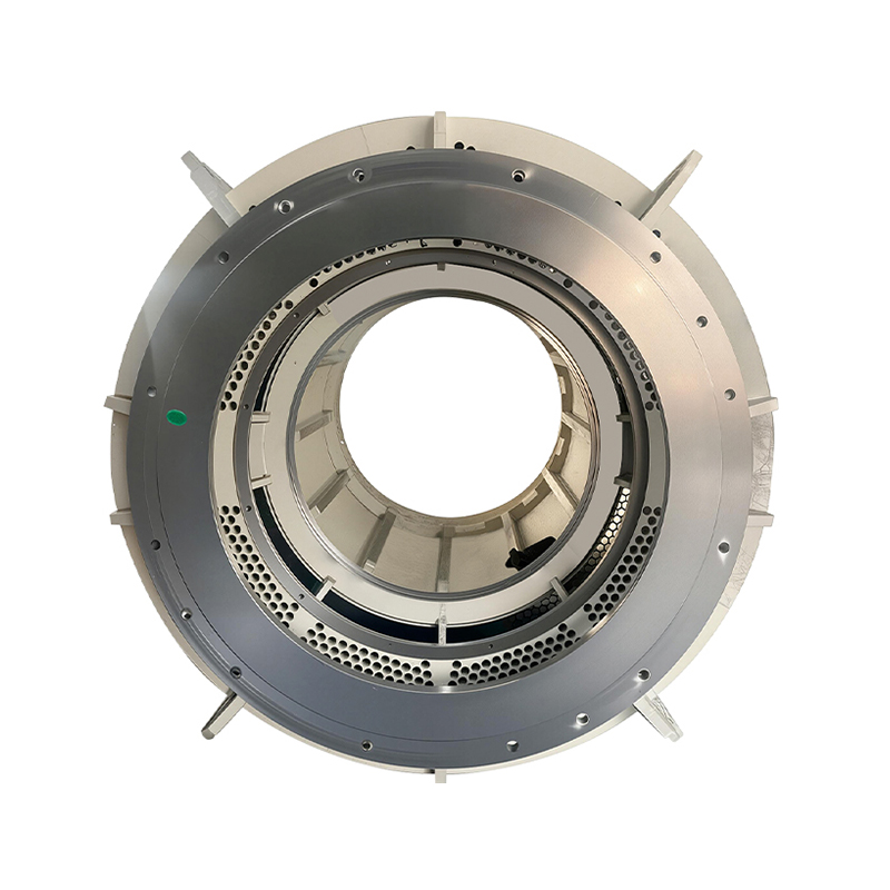
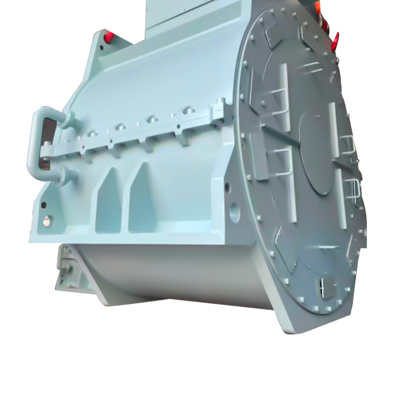
Direct-Drive Turbine Generator Frames
Direct-drive wind turbines eliminate the gearbox entirely, with the rotor hub connecting directly to a large-diameter, low-speed generator. The wind turbine generator frame in direct-drive configurations takes on an even more critical structural role — it must support a generator that is significantly larger and heavier than its geared equivalent (often 50 to 100 tonnes in offshore multi-megawatt machines) while maintaining the precise air gap uniformity between rotor and stator that is essential for electromagnetic efficiency and avoiding rotor-stator contact. The structural frame in direct-drive turbines often integrates with the main bearing housing and forms a continuous load path from the rotor hub to the tower top, making it one of the most complex structural castings or fabrications in the entire turbine.
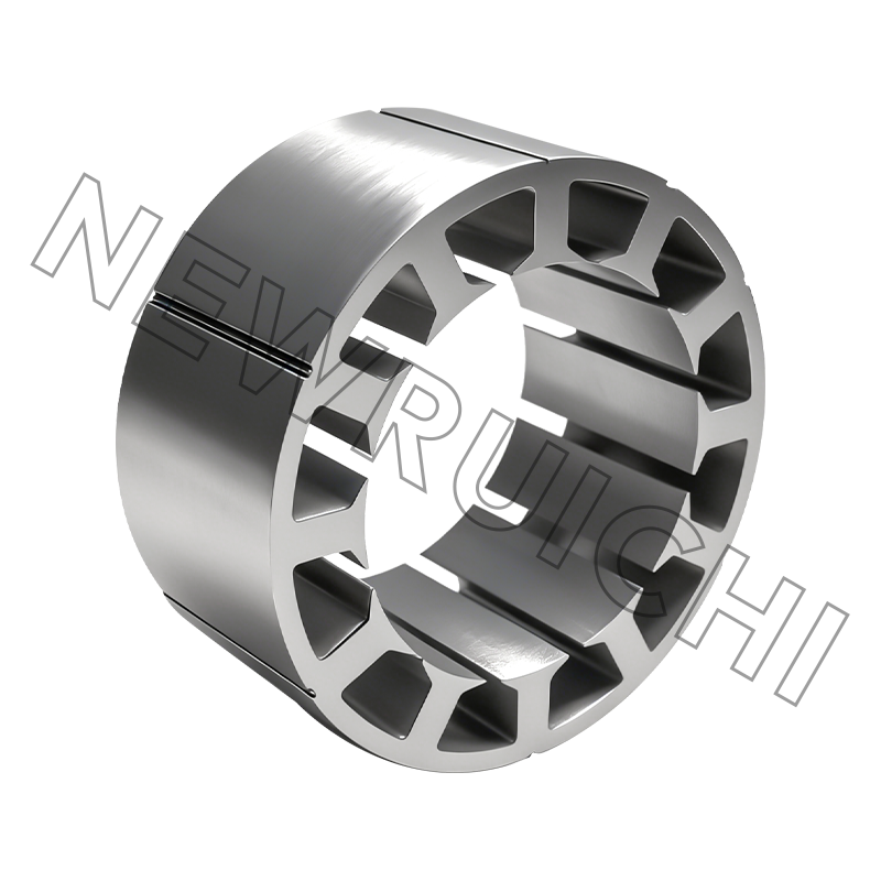
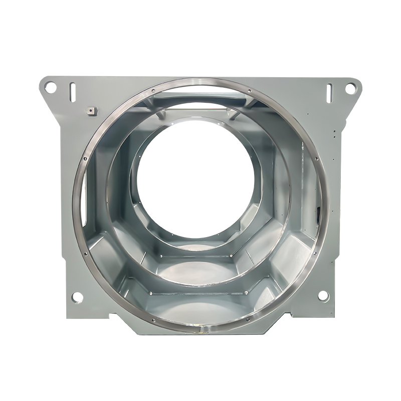
Materials and Manufacturing Methods for Generator Housings
The material and manufacturing process selected for a wind turbine generator housing must satisfy simultaneous requirements for structural strength, stiffness, fatigue resistance, dimensional accuracy, weldability or castability, and machinability at the precision interfaces where the generator and drivetrain components mount. Two primary manufacturing routes dominate current production: structural steel fabrication and ductile iron casting.
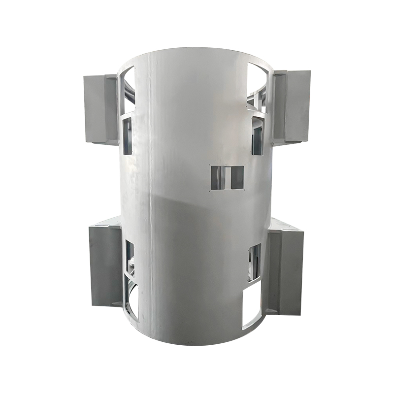
Structural Steel Fabricated Frames
Steel-fabricated wind turbine generator frames are constructed from plate and structural steel sections, cut to profile and welded into the required three-dimensional geometry. This approach offers design flexibility — the frame geometry can be optimized in detail without the constraints of casting feasibility — and is well-suited to low and medium production volumes where tooling investment for casting would not be justified. High-strength structural steel grades — S355 and S420 being common specifications — provide the yield strength and toughness required for the fatigue loading environment. Weld quality is the critical manufacturing variable in fabricated frames; all structural welds must meet EN ISO 5817 quality level B as a minimum, with full penetration weld inspection by ultrasonic or radiographic testing at high-stress locations.
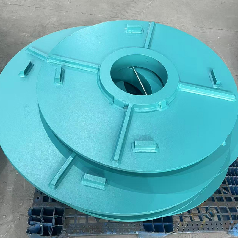
Ductile Iron Cast Frames
For higher production volumes, ductile iron casting offers significant advantages in producing the complex three-dimensional geometries of the wind turbine generator frame with integrated ribs, bosses, and mounting pads that would be extremely difficult to achieve in fabricated construction. Grade EN-GJS-400-18-LT ductile iron — selected for its combination of strength, ductility, and low-temperature impact resistance for cold-climate installations — is the standard material specification. Cast frames achieve their final dimensional accuracy through precision machining of all critical mounting interfaces, with tolerances on generator mounting pad flatness typically held to within 0.05mm across the full mounting footprint.
| Property | Steel Fabricated Frame | Ductile Iron Cast Frame |
| Geometric complexity | Moderate — limited by fabrication | High — complex internal features possible |
| Tooling investment | Low | High (pattern and core tooling) |
| Unit cost at volume | Higher | Lower |
| Lead time flexibility | High — no pattern lead time | Lower — foundry scheduling dependent |
| Design modification | Fast and low cost | Slow and expensive (pattern rework) |
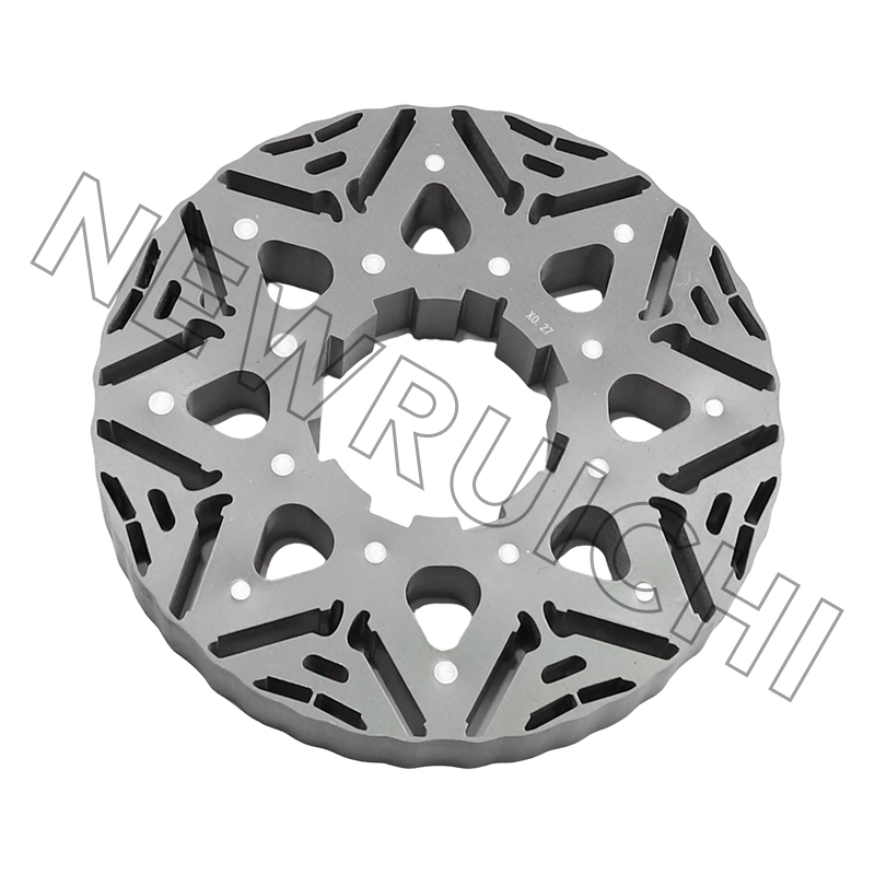
Precision Alignment Requirements and Machining Standards
The wind turbine generator frame ensures precise alignment and positioning between the generator and the gearbox or main shaft — a requirement that translates into extremely demanding machining specifications for the frame's mounting interfaces. Achieving and maintaining this alignment over the turbine's 20-year service life requires that the machined surfaces retain their dimensional accuracy despite the structural deflections, thermal cycles, and fatigue loads accumulated during operation.
Critical machined features on the wind turbine generator housing include the generator mounting pad faces — which must be co-planar within tight flatness tolerances to ensure even load distribution across all mounting bolts — and the alignment bore or register features that locate the generator concentrically relative to the drivetrain centerline. Positional tolerances on alignment features are typically specified in the range of ±0.1mm to ±0.2mm, achieved through precision CNC horizontal boring and milling operations using large-format machining centers capable of accommodating the full frame envelope in a single setup. Single-setup machining of all critical interfaces eliminates the cumulative positional errors that would result from repositioning the workpiece between operations, and is considered the only reliable method for achieving the required inter-feature accuracy on large generator frames.
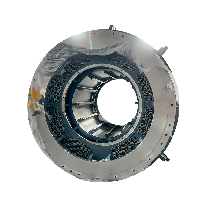
Surface Protection and Corrosion Prevention for Harsh Environments
Wind turbines operate in some of the harshest corrosive environments encountered by industrial equipment — offshore installations face constant salt spray and high humidity, while onshore installations in coastal, desert, and cold-climate regions present their own corrosion challenges. The wind turbine generator housing must be protected against corrosion throughout its service life without requiring coating maintenance that would necessitate major disassembly of nacelle components.
Surface protection systems for generator frames in standard onshore applications typically consist of a zinc-rich primer applied by airless spray to a minimum dry film thickness of 60 microns, followed by epoxy intermediate coats and a polyurethane topcoat, achieving a total system thickness of 200 to 320 microns in accordance with ISO 12944 corrosivity category C3 or C4. Offshore installations require enhanced protection systems meeting C5-M requirements — often incorporating thermally sprayed zinc or aluminum as an additional barrier under the paint system — to achieve the 25-year maintenance-free corrosion protection that inaccessible offshore nacelle components demand. Machined surfaces and precision interfaces are protected with removable preservative compounds during storage and transport, removed during installation to restore the dimensional accuracy of the mounting surfaces.
Quality Assurance and Certification for Generator Frame Production
Wind turbine generator frames are safety-critical components subject to certification requirements from independent type certification bodies — including DNV, Bureau Veritas, TÜV SÜD, and Lloyd's Register — whose approval is required before turbine designs can be commercially deployed. The quality assurance requirements for generator frame production are correspondingly rigorous, covering material traceability, non-destructive examination, dimensional inspection, and documented process controls at every stage of manufacture.
- Material certification — All structural steel plate and sections must be supplied with EN 10204 3.2 material test certificates, verified by an independent inspecting authority, confirming chemical composition, mechanical properties, and impact test results at the specified test temperature.
- Weld procedure and welder qualification — All structural welding must be performed to qualified weld procedure specifications (WPS) developed and tested in accordance with EN ISO 15614, with all welders holding current qualification certificates for the relevant weld process, material group, and joint configuration.
- Non-destructive examination (NDE) — Full-penetration welds at high-stress locations are subjected to ultrasonic testing (UT) or radiographic testing (RT) to detect internal defects. Magnetic particle testing (MT) is applied to all weld toes and high-stress surface areas to detect surface-breaking and near-surface cracks that could initiate fatigue failures.
- Dimensional inspection report — A full dimensional inspection report, generated using CMM measurement of all critical features, is produced for each generator frame and retained as a quality record that supports the turbine's certification documentation and provides a baseline for any future condition assessment.
Your email address will not be published. Required fields are marked *


![]() Email: [email protected]
Email: [email protected]
[email protected]
[email protected]
![]() Telephone/Phone:
+86-18861576796 +86-18261588866
Telephone/Phone:
+86-18861576796 +86-18261588866
+86-15061854509 +86-15305731515
Copyright © Wuxi New Ruichi Technology Co., Ltd. / Wuxi Cailiang Machinery Co., Ltd. All rights reserved.
Stator And Rotor Cores Manufacturers
