 en
en
 русский
 Deutsch
Marine Motor Housings: Corrosion Protection & Design Guide
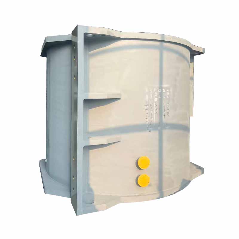
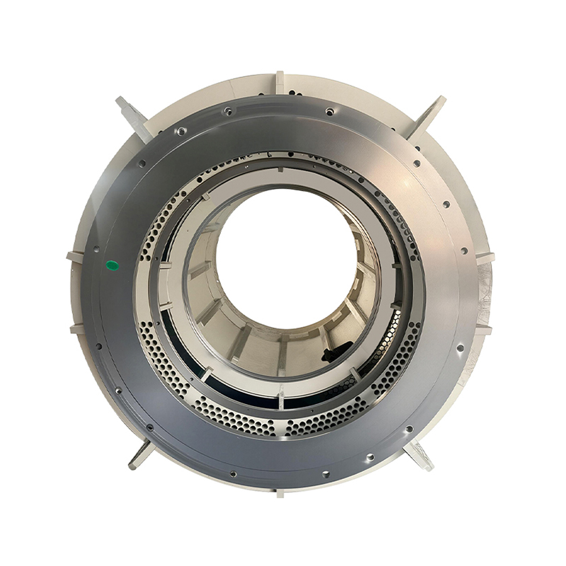
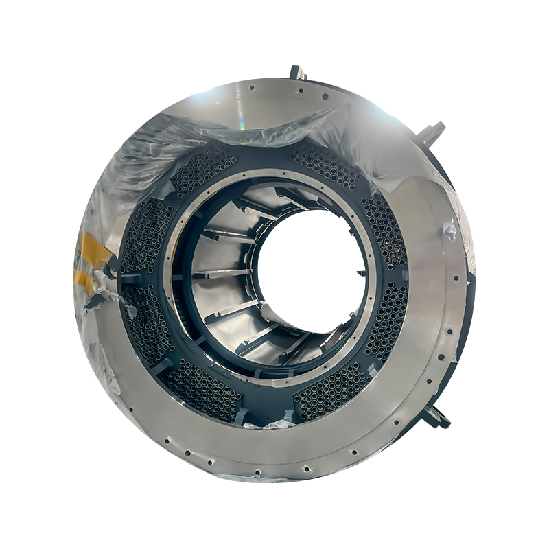
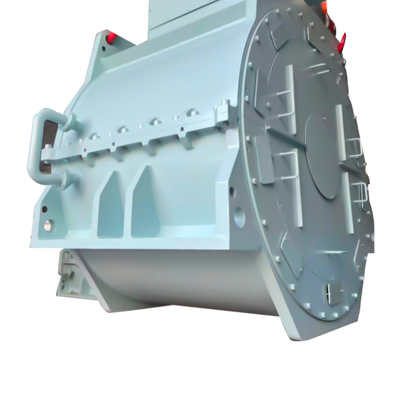
Marine motor housings serve a single critical function: to isolate the motor's stator, rotor, bearings, and windings from an environment that actively destroys unprotected metal. Salt spray, continuous humidity above 90% relative humidity, diesel and lubricating oil mist, and temperature swings from sub-zero Arctic waters to tropical engine rooms create a combination of corrosion mechanisms that land-based motor enclosures never encounter. A properly specified marine motor housing addresses this through material selection, surface treatment, sealing geometry, and structural reinforcement that together deliver a service life of 15–25 years even aboard oceangoing vessels with minimal maintenance intervals. The housing must simultaneously satisfy classification society requirements—Lloyd's Register, DNV, ABS, BV, and others—while providing the mechanical rigidity that maintains the precise air gap between stator and rotor under hull flexure and wave-induced vibration.
Content
- 1 Material Selection for Marine Service Conditions
- 2 Ingress Protection and Sealing for Maritime Conditions
- 3 Explosion-Proof Housing Requirements for Hazardous Zones
- 4 Heat Dissipation in Confined Marine Spaces
- 5 Structural Rigidity and Vibration Resistance
- 6 Classification Society and Regulatory Compliance
- 7 Inspection and Maintenance of Marine Motor Housings
Material Selection for Marine Service Conditions
The choice of housing material determines baseline corrosion resistance before any coating is applied. Three material categories dominate marine motor construction, each suited to different vessel zones and operating conditions.
Cast Iron with Protective Coatings
Grey cast iron (GJL-200 or GJL-250 grade) remains the most common housing material for marine motors in engine rooms and pump compartments where cost considerations balance against adequate performance. The material offers good vibration damping—its graphite flake structure absorbs vibration energy at 5–10 times the rate of steel—which reduces noise transmission and protects the stator core from fatigue cracking. Cast iron's limitation is its susceptibility to graphitic corrosion in saltwater immersion conditions, where the iron matrix corrodes preferentially, leaving a weakened graphite skeleton. Marine-spec cast iron housings counter this with multi-layer coating systems: a zinc-rich epoxy primer providing cathodic protection, followed by high-build epoxy intermediate coats, and finished with a two-component polyurethane topcoat. Total dry film thickness typically exceeds 250–350 µm, and salt spray resistance per ISO 9227 exceeds 1,000 hours before scribe creep reaches 3 mm. This coating package, combined with regular freshwater wash-downs, allows cast iron housings to serve reliably in machinery spaces for the vessel's operational life.
Stainless Steel for Deck and Open-Area Applications
Motors exposed to direct weather on open decks, offshore platforms, and cargo handling areas demand stainless steel housings. Grade 316L (EN 1.4404) austenitic stainless steel is the standard marine specification, containing 2–3% molybdenum that provides pitting resistance in chloride environments. The pitting resistance equivalent number (PREN) for 316L is 24–26; marine environments require a minimum PREN of 32 for prolonged immersion service, but deck-mounted equipment above the splash zone performs adequately at the 316L level when combined with regular freshwater rinsing. Stainless steel housings eliminate the coating degradation failure mode entirely, though they introduce a different risk: crevice corrosion at gasket surfaces and bolt holes where stagnant seawater can concentrate chlorides. Proper design mitigates this with sloped drainage paths and the use of molybdenum-disulfide anti-seize compounds on all stainless steel fasteners to prevent galling during assembly.
Aluminum Alloys for Weight-Sensitive Installations
On high-speed craft, naval vessels, and offshore helicopter decks where weight directly impacts fuel consumption and stability, marine-grade aluminum alloys replace ferrous materials. Alloy EN AW-6082 (AlSi1MgMn) offers a yield strength of 250–280 MPa in the T6 temper at roughly one-third the weight of cast iron. The natural formation of a passive aluminum oxide layer provides inherent corrosion resistance, but this layer breaks down in the presence of chlorides if copper or iron contaminants are present. Marine aluminum housings require hard anodizing to a thickness of 25–50 µm or a two-part epoxy coating system to isolate the aluminum from direct salt contact. The critical design consideration with aluminum housings is galvanic isolation: any direct contact between the aluminum housing and steel mounting bolts or bronze cable glands in the presence of moisture creates a galvanic cell where the aluminum corrodes sacrificially. Insulating washers, nylon bolt sleeves, and dielectric gaskets are mandatory at all dissimilar metal interfaces.
Ingress Protection and Sealing for Maritime Conditions
Marine motor housings must prevent water and particulate ingress under conditions far more severe than the IP (Ingress Protection) testing laboratory. The combination of salt-laden humidity, high-pressure deck washing, and occasional green-water immersion demands sealing designs that exceed minimum classification society requirements.
| Motor Location | Minimum IP Rating | Primary Protection Against | Sealing Features Required |
|---|---|---|---|
| Enclosed Engine Room | IP44–IP54 | Oil mist, condensation, occasional splash | Labyrinth seals, shaft flinger rings, drain plugs |
| Pump Room / Bilge Area | IP56 | Heavy water spray, bilge water immersion risk | Double-lip shaft seals, O-ring housing joints, stainless steel breather drains |
| Open Deck / Weather-Exposed | IP66 | Heavy seas, driven rain, hose-directed water | Compression gaskets on all joints, sealed terminal box with cable gland IP66 rated |
| Offshore Platform Hazardous Zone | IP66 + Ex-d or Ex-e | Gas ingress, pressure piling from internal explosion | Flamepath joints, certified cable entries, anti-static coatings |
The shaft seal represents the most vulnerable ingress point because it must accommodate continuous rotation while excluding moisture. Marine-duty housings use a combination of a V-ring or labyrinth seal on the exterior, which deflects bulk water and contaminants through centrifugal action as the shaft rotates, backed by a lip seal with a stainless steel garter spring that maintains contact pressure even after the elastomer takes a compression set. In particularly aggressive locations, a bearing isolator with an O-ring static seal and a labyrinth dynamic seal provides non-contacting protection that never wears, maintaining its IP rating over the motor's entire service interval.
Explosion-Proof Housing Requirements for Hazardous Zones
On oil tankers, FPSO vessels, gas carriers, and offshore drilling platforms, motor housings must prevent any internal spark or arc from igniting the surrounding flammable atmosphere. This requirement transforms the housing from a simple protective enclosure into a precision-engineered pressure vessel. Explosion-proof (Ex-d) marine motor housings are designed so that an internal explosion of the specified gas group—typically IIB (ethylene) or IIC (hydrogen/acetylene) for the most demanding offshore applications—is contained entirely within the housing. The flamepath, the precisely machined gap between the housing and its end shields, must be long enough and tight enough that any hot gases escaping through the joint cool below the ignition temperature of the external atmosphere before reaching it. For IIC gases, this gap is restricted to 0.15–0.20 mm maximum with a minimum flamepath length of 13–25 mm depending on the internal volume. These tolerances demand CNC machining of the housing joint faces and 100% dimensional inspection before certification.
The housing must also withstand the explosion pressure without permanent deformation. Hydrostatic pressure testing at 1.5 times the maximum explosion pressure—typically 15–20 bar for IIB and 25–30 bar for IIC enclosures—verifies structural integrity. Marine explosion-proof housings often exceed these minimums by incorporating additional wall thickness in recognition that salt corrosion may reduce section thickness over decades of service. The terminal box receives separate Ex-e (increased safety) or Ex-d certification, with the cable entry glands individually certified and assembled with the correct sealing washers and compression rings. Each housing carries a certification plate listing the gas group, temperature class, and certifying body reference—a plate that must remain legible for the life of the motor despite salt exposure, requiring embossed stainless steel rather than printed aluminum labels.
Heat Dissipation in Confined Marine Spaces
Marine motor housings face a thermal design challenge that land-based motors rarely encounter: they operate in engine rooms where ambient air temperatures routinely reach 45–55°C, with cooling air drawn from spaces already heated by running machinery. The housing must reject the motor's internal losses—copper I²R losses, core losses, and friction and windage losses—to this already hot environment while maintaining winding temperatures below the insulation class limit. For Class F insulation (155°C hot spot), the allowable temperature rise at 45°C ambient is 105 K, but marine designers typically aim for Class F rise with Class H (180°C) insulation to build in thermal reserve for fouled cooling passages or temporary overloads.
The housing contributes to heat dissipation through its external cooling ribs or fins, which increase the surface area available for convective and radiant heat transfer. A well-designed marine motor housing increases its effective cooling surface area by 200–400% through ribbing compared to a smooth cylindrical envelope of the same dimensions. The rib profile—height, spacing, and orientation—must balance heat transfer against the accumulation of salt and dust between ribs, which degrades cooling performance and accelerates corrosion. Vertically oriented ribs with spacing greater than 15 mm allow natural convection to carry heat upward while minimizing debris trapping. In TEFC (Totally Enclosed Fan-Cooled) marine motors, an external shaft-mounted fan blows air axially over the ribbed housing surface, improving the convective heat transfer coefficient from roughly 5–10 W/m²K for natural convection to 30–50 W/m²K. The fan cowl becomes part of the thermal management system, directing airflow evenly across all ribs rather than allowing it to bypass the housing.
Structural Rigidity and Vibration Resistance
Marine motor housings must maintain dimensional stability under loads that land-based motors never experience. A vessel's hull flexes continuously as it passes through waves, with deflection amplitudes that can reach 2–5 mm across the length of a large motor mounted on a common bedplate. The housing structure must tolerate this flexure without distorting the stator bore or altering the rotor-to-stator air gap. A housing cast with integrally reinforced mounting feet and internal ribbing connecting the feet to the stator frame resists torsional deformation better than welded fabrications, which can develop fatigue cracks at the weld toes under cyclic loading. Classification societies require vibration testing per IEC 60034-14, with vibration velocity limits of 2.8 mm/s RMS for standard motors and 1.8 mm/s for precision-balance applications. Meeting these limits in a marine environment requires not just a rigid housing but precision alignment of the end shields that position the rotor bearings concentric with the stator bore within 0.05 mm total indicated runout.
Shock resistance adds a further structural requirement, particularly for naval vessels and offshore platforms subject to underwater explosion or wave slam loads. MIL-S-901D shock testing or equivalent classification society shock standards require the motor housing to survive acceleration pulses of 20–50 g without loss of structural integrity or functional performance. Housing designs that pass these tests typically incorporate additional wall thickness in stress concentration zones, radiused transitions between sections rather than sharp corners, and material specifications with guaranteed Charpy impact values at low temperatures—important for vessels operating in Arctic waters where steel transitions from ductile to brittle fracture behavior.
Classification Society and Regulatory Compliance
A marine motor housing cannot simply be claimed as marine-grade; it must carry documented certification from the classification society that surveys the vessel. The major societies—Lloyd's Register, DNV, Bureau Veritas, American Bureau of Shipping, and ClassNK—maintain type approval programs that verify housing design, materials, manufacturing quality control, and performance testing. The approval process requires submission of detailed drawings showing housing dimensions, material certificates for each heat of metal used, non-destructive testing reports for critical welds or castings, and witnessed performance tests. Type approval is vessel-specific in the sense that the society must verify the motor is suitable for the intended service: a motor approved for an engine room ventilation fan may not be automatically accepted for a cargo pump room where flammable vapors may be present.
Beyond classification society rules, marine motor housings must comply with SOLAS (Safety of Life at Sea) regulations and IEC 60092 series standards for electrical installations aboard ships. These mandate specific requirements for earthing terminals, cable gland arrangements, and creepage and clearance distances within terminal boxes that differ from land-based IEC 60034 standards. The housing design must incorporate a dedicated internal earth continuity conductor or a tested earth path through the metallic housing structure, with resistance from any accessible metal part to the main earthing terminal not exceeding 0.1 ohms. The terminal box must be sized to accommodate the bending radius of the specified cable type—an apparently minor detail that, if overlooked, prevents the cable gland from sealing properly and voids the housing's IP rating from the moment of installation.
Inspection and Maintenance of Marine Motor Housings
Even the most corrosion-resistant housing requires a structured inspection regime to deliver its design life. Marine surveyors and vessel engineers follow a condition-based monitoring approach that examines the housing at each major survey interval—typically annual for cargo ships and every 2–3 years for passenger vessels during dry-docking. The inspection checklist addresses the housing's protective functions systematically: coating integrity assessed by ISO 4628 standards for rusting and blistering, gasket condition verified by physical compression set measurement, flamepath dimensions rechecked on explosion-proof housings using feeler gauges and compared to the original certification records, and earth continuity resistance measured and logged. Any coating breakdown that exposes bare metal requires restoration to the original specification, not a cosmetic overspray that leaves active corrosion cells under the new paint film. Drain plugs must be removed and cleaned; blocked breather drains are a leading cause of internal condensation damage because they trap water inside the housing rather than allowing it to drain as designed. A well-maintained marine motor housing on a 20-year-old vessel should show no structural metal loss, no measurable increase in air gap eccentricity from the original commissioning records, and earth continuity values unchanged from the factory test certificate.
Your email address will not be published. Required fields are marked *



 Email: [email protected]
[email protected]
 Telephone/Phone:
+86-18861576796 +86-18261588866
Telephone/Phone:
+86-18861576796 +86-18261588866
+86-15305731515 +86-18861576796
Copyright © Wuxi New Ruichi Technology Co., Ltd. / Wuxi Cailiang Machinery Co., Ltd. All rights reserved.
Stator And Rotor Cores Manufacturers
