 en
 русский
 Deutsch

3 Phase Motor Wiring: Star or Delta, Six-Lead Connections, and Rotation
A 22 kW conveyor motor arrives on site with nine leads poking out of the terminal box, a nameplate stamped 400/690 V, and no wiring diagram in the crate. The electrician has a 400 V supply, three lugs, and a line that has to move in twenty minutes. Everything that matters here is already printed on the nameplate or sitting inside that box.
Three-phase motor wiring reduces to three questions: should the windings sit in star or delta, which two leads do you swap to reverse rotation, and how is the motor going to start. Get those three right and the rest is torque figures and insulation checks.
The conclusion, up front
- Nameplate reads 400/690 V and the supply is 400 V: connect in delta. Link W2 to U1, U2 to V1, V2 to W1.
- Nameplate reads 230/400 V and the supply is 400 V: connect in star. Short W2, U2 and V2 together at the common point.
- Rotation is wrong: swap any two of L1, L2 and L3 at the supply terminals. Never rewire the winding links to fix direction.
- Star-delta starting needs all six leads brought out to the contactor set. Direct-on-line needs three leads plus a protective earth.
Content
- 1 Why Six Leads Change Everything
- 2 The Wiring Sequence, Step by Step
- 3 Star Versus Delta: The Numbers Side by Side
- 4 Hidden Indicators: What the Clamp Meter Says in the First Two Seconds
- 5 Where Three-Phase Motors Actually Run
- 6 What the Wiring Job Cannot Fix
- 7 Selection Snapshot: Which Motor Core Suits the Job
- 8 Maintenance and Compliance: Keeping the Winding Alive
Why Six Leads Change Everything
A three-phase motor contains three separate phase windings. Bringing six leads to the terminal block means both ends of every winding are accessible, so you get to choose how those windings sit relative to the supply.
In star, the three winding tails join at a common point. Each winding sees only the phase voltage, which is the line voltage divided by 1.732. On a 400 V supply that is 231 V across each winding, and the line current equals the current flowing inside each winding. In delta, the tails connect to the next winding head, so every winding sits directly across the full 400 V line voltage and carries 1.732 times the line current of the star connection at the same output.
That arithmetic decides everything downstream. A motor wound for 400 V delta but mistakenly linked in star on a 400 V supply only pushes 231 V through each winding, which collapses the air-gap flux and drops torque to roughly a quarter of the nameplate value. The motor usually still turns, which is exactly why the mistake survives long enough to overheat a pump or stall a conveyor under load.
Star (Y)
Winding voltage is line voltage divided by 1.732. Lowest starting current, lowest starting torque. The correct link for a 230/400 V nameplate on a 400 V system.
Delta (Δ)
Winding voltage equals full line voltage. Full torque and full current. The correct link for a 400/690 V nameplate on a 400 V system.
Star-delta
Starts in star, runs in delta. Starting current and starting torque each fall to about one third of the delta-on-line value. Six leads must reach the contactors.
The Wiring Sequence, Step by Step
The order matters more than the speed. A terminal block rewired live is how most of the avoidable failures in this job start.
01 — Isolate and prove dead. Lock off the starter, then test phase-to-phase and phase-to-earth at the supply terminals with a proven meter.
02 — Read the nameplate. Record the voltage ratio, frequency, connection symbol and duty. The ratio tells you which link to fit; nothing else does.
03 — Identify the leads. IEC machines use U1/V1/W1 for the heads and W2/U2/V2 for the tails. NEMA machines use T1/T2/T3 and T4/T5/T6. The logic is identical.
04 — Fit the links. Lay the brass links flat for star, vertical for delta. Torque them to the figure stamped inside the terminal cover.
05 — Bring in the supply. L1, L2, L3 to U1, V1, W1. Earth conductor to the PE stud, sized to local code.
06 — Bump it, then run it. A one-second jog reveals rotation direction. If it is backwards, swap L1 and L3, then log the no-load current against nameplate full-load amps.
Star Versus Delta: The Numbers Side by Side
The table below assumes one motor, one supply, and the same load. Only the winding links change.
Hidden Indicators: What the Clamp Meter Says in the First Two Seconds
Inrush current is the least visible and most diagnostic part of a three-phase motor startup. The multiple of full-load current drawn in the first two seconds tells you which starting method is really installed, and whether the winding connection matches it.
A delta motor that shows roughly a fivefold inrush instead of sevenfold is usually reading a star-linked terminal block that nobody corrected. A delta motor that shows a steady 1.3× no-load current on a 400 V supply is a strong candidate for a star-delta motor running permanently in star, which explains the slow ramp on a loaded conveyor and the extra heat in the winding.
Where Three-Phase Motors Actually Run
Wiring practice follows the application more than the motor. Pump and fan duty rewards energy efficiency, material handling rewards starting torque, and marine duty rewards corrosion protection across the whole assembly, terminal box included.
- 30% Pumps and fans — mostly direct-on-line delta or VFD driven.
- 18% HVAC and refrigeration — star-delta and soft starters dominate.
- 15% Conveyors and material handling — direct-on-line delta, high starting torque.
- 12% Machine tools — star-delta with reversing contactors.
- 10% Marine and offshore — enclosed terminal boxes, corrosion-rated frames.
- 8% Wind and new energy generation — permanent magnet and wound-rotor designs.
- 7% Other industrial duty — mining, cement, and heavy processing.
What the Wiring Job Cannot Fix
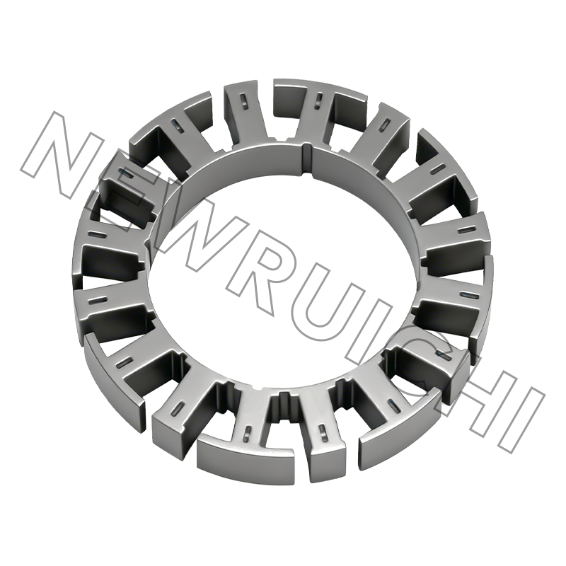
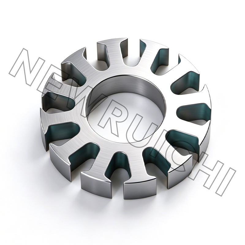
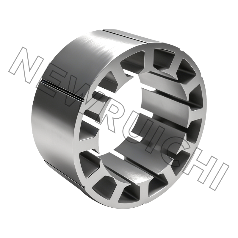
A clean terminal block cannot rescue a poor stator core. Once the links are correct, three things decide whether the winding survives: the slot geometry that carries the copper, the insulation between phases, and the lamination stacking factor that sets the magnetic path. Buyers who only audit the wiring diagram tend to discover this at the first thermal trip.
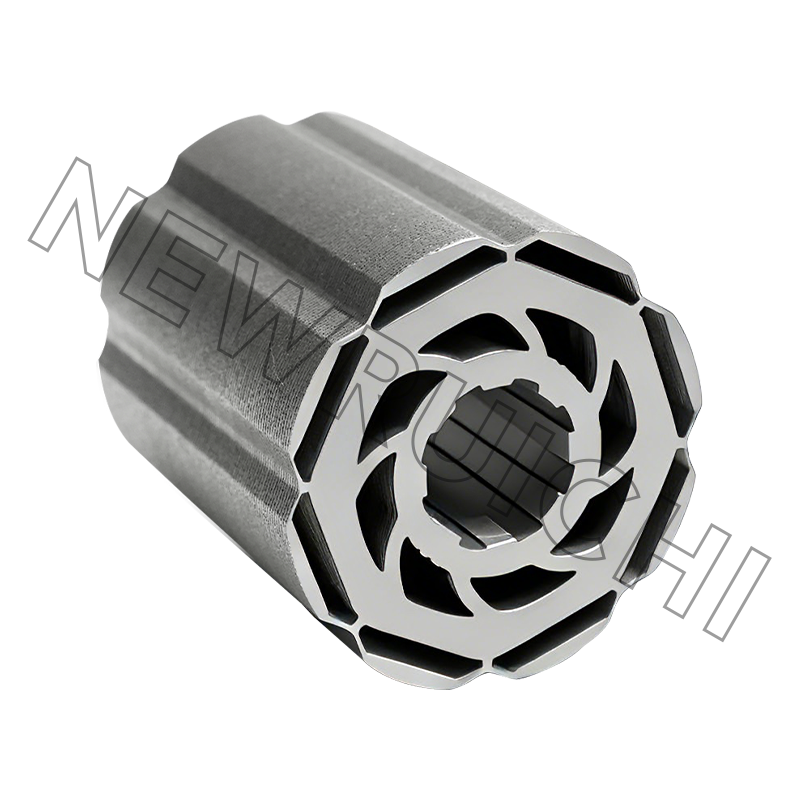
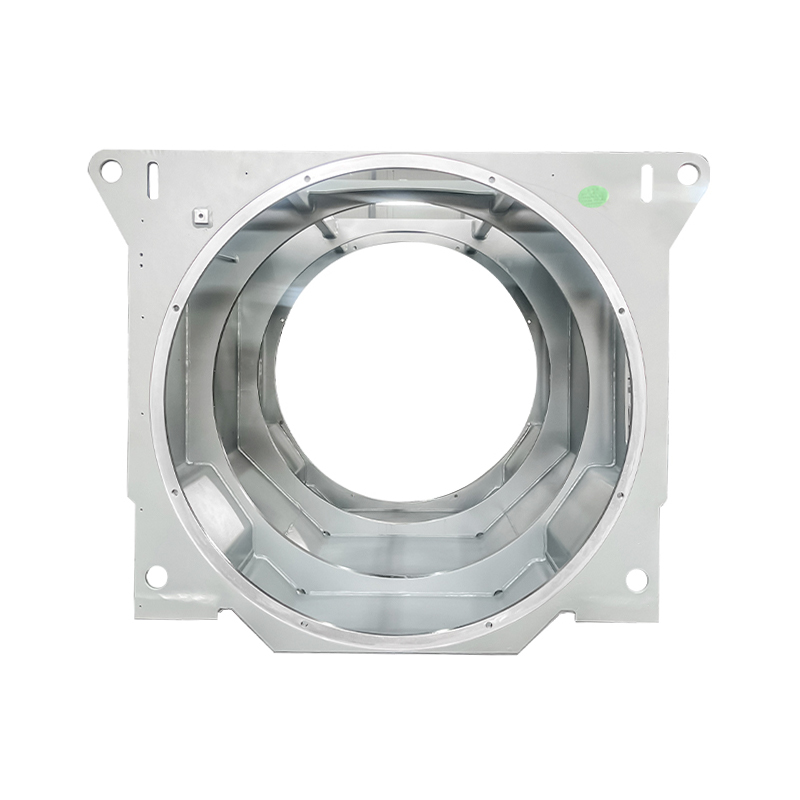
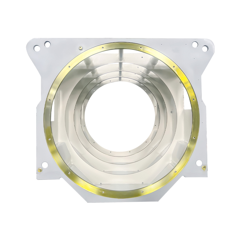
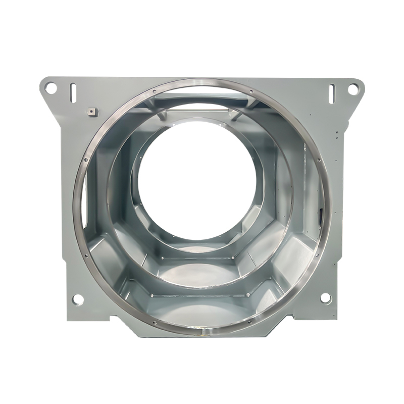
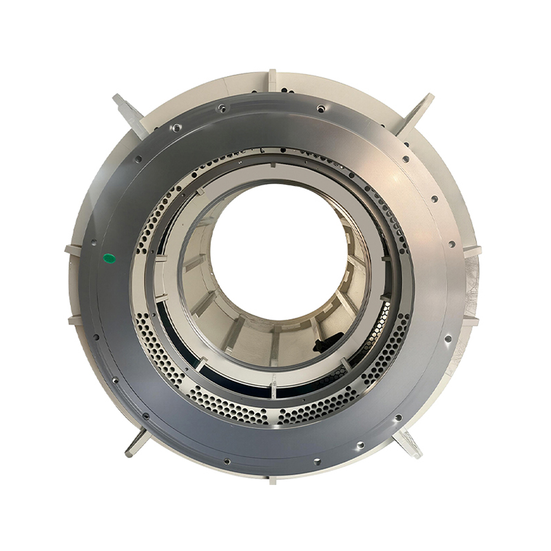
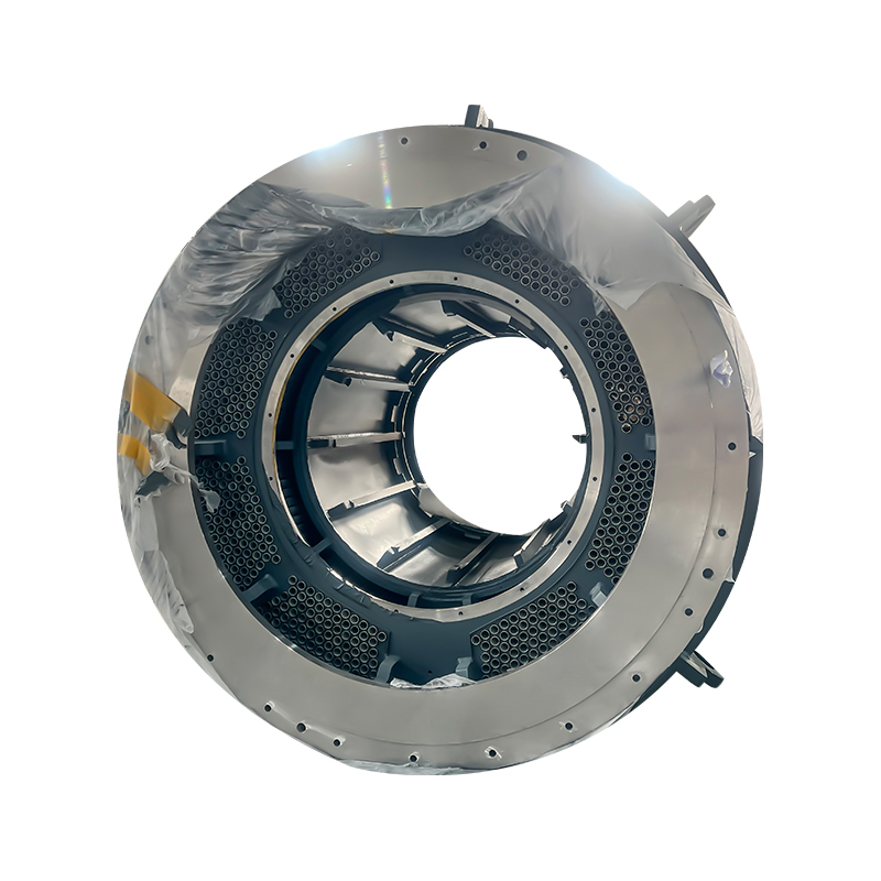
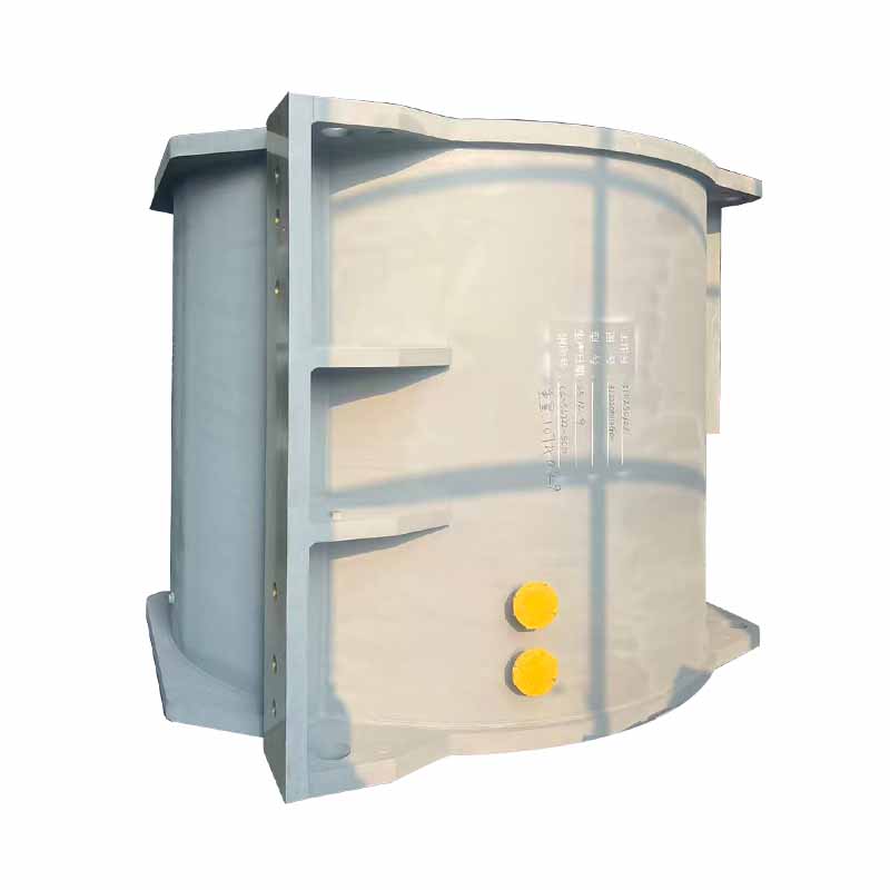
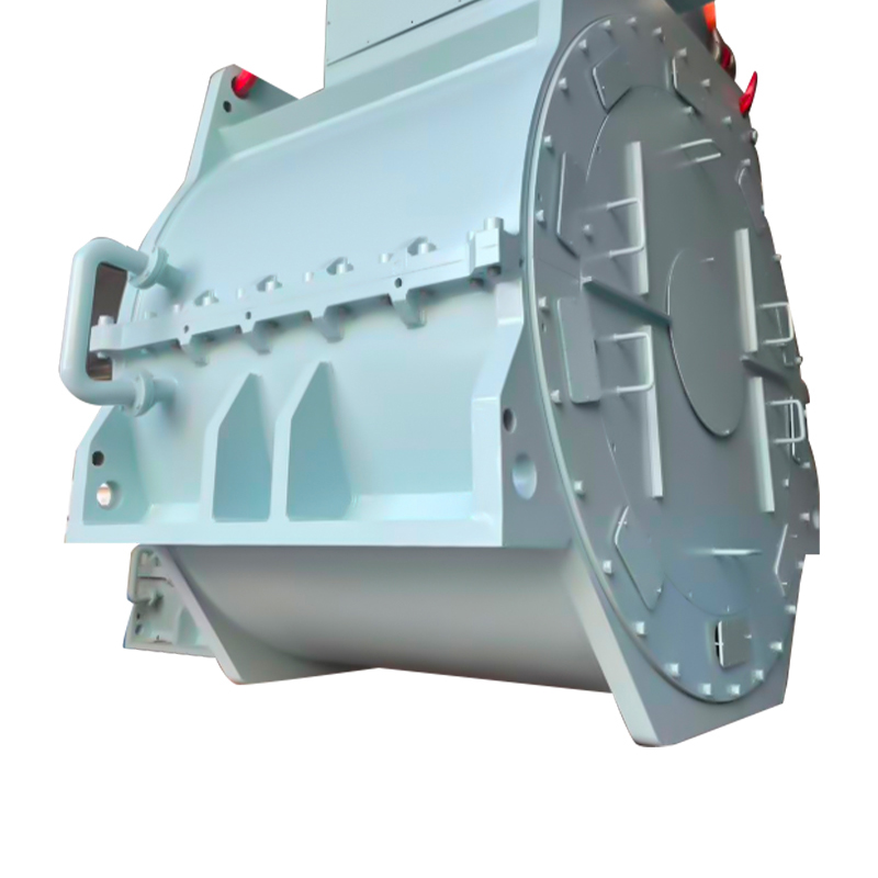
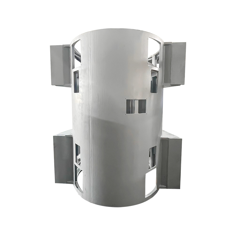
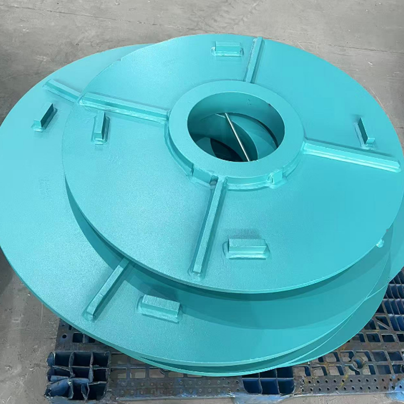
This is where the upstream supplier matters. Companies such as Wuxi New Ruichi and Wuxi Cailiang sit at the motor and transformer component level rather than the finished-machine level, supplying the punched lamination and assembled cores that the winding is later built into. Their product range covers AC, DC, servo, stepper and new-energy-vehicle stator and rotor cores, transformer cores, silicon steel strip, welded box-type frames, end closures and cooling fans, backed by ISO 9001, IATF 16949, ISO 14001 and ISO 3834 certification.
For an engineer specifying a motor for a demanding duty cycle, the practical guidance is straightforward: specify the core geometry and the slot insulation class before you specify the starting method. The connection diagram is the last 10% of the problem. Anyone who has debugged an intermittent phase-to-phase fault knows how much of the cost sits in the other 90%, and a readable primer on stator core construction is a faster route to that understanding than another wiring diagram.
Selection Snapshot: Which Motor Core Suits the Job
The right core depends on how the motor starts and how long it has to last. The options below cover the most common industrial duties.
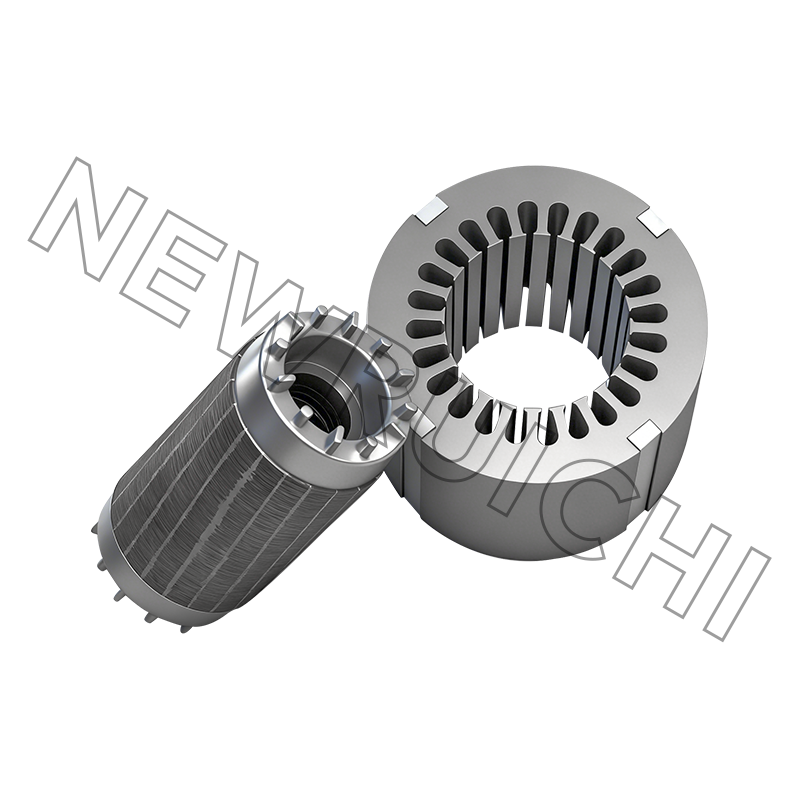
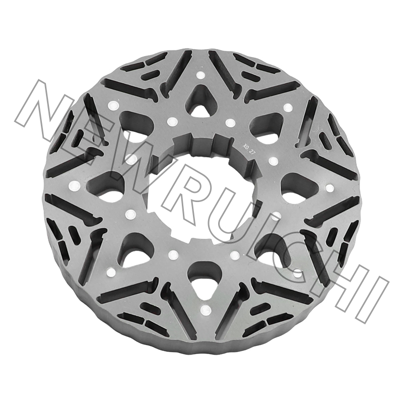
 AC Motor Stator and Rotor Core Assemblies for Industrial MotorsStacked non-oriented silicon steel laminations for AC motors, relevant when matching core construction to industrial duty, efficiency, and downstream insulation standards.View Product →
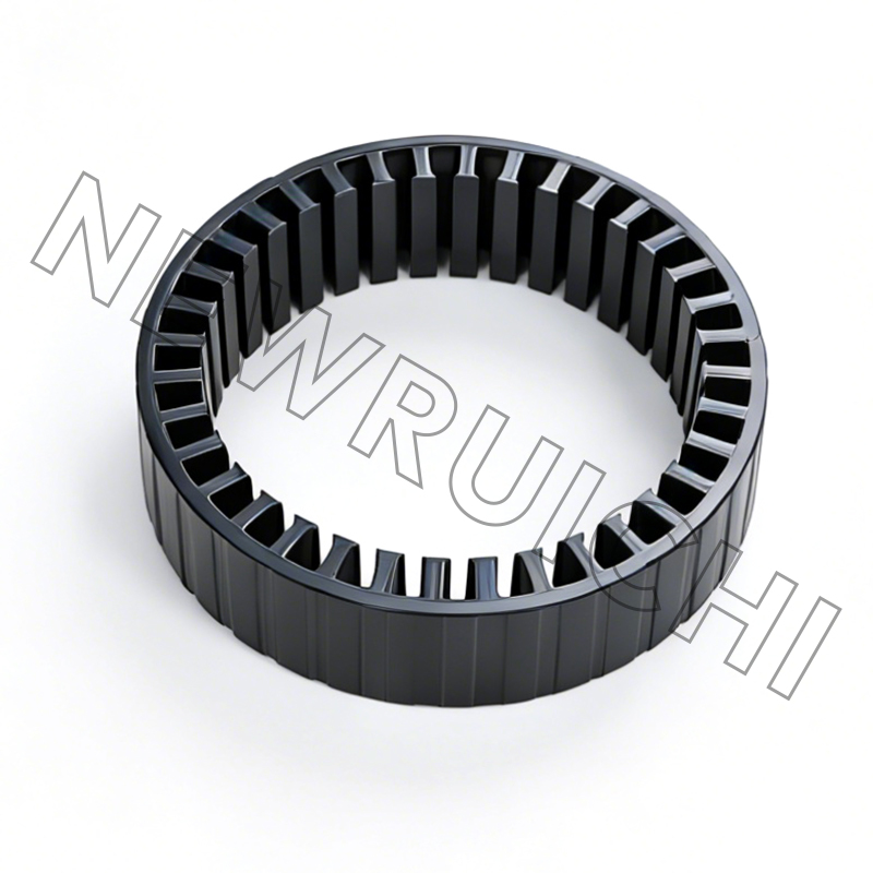
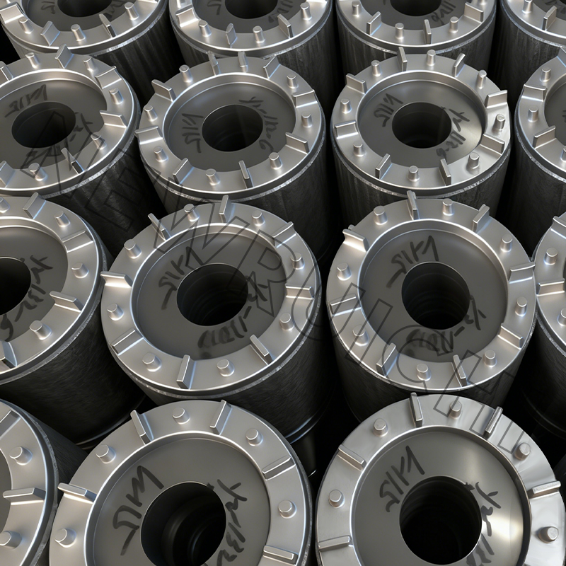 Interlock Laminated Cores for High-Performance Motors and TransformersWeld-free, glue-free interlocked laminations support uniform magnetic paths and mass production, worth viewing for industrial-duty motors, transformers, and magnetic components.View Product →
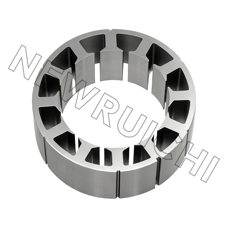
 Silicon Steel Rolls, Strips, and Sheets for Motor LaminationsQuality-controlled silicon steel rolls, strips, and sheets for motor cores and precision stamping, worth viewing for common industrial-duty material selection and efficient production.View Product →
Maintenance and Compliance: Keeping the Winding Alive
Wiring standards and insulation standards are separate documents, and both apply. IEC 60034-8 governs terminal markings and rotation; IEC 60034-27 covers insulation testing. The checks below map back to those documents and to what actually fails in the field.
Insulation resistance
Test with a 500 V or 1000 V insulation tester before energising and after any rework. A widely used rule of thumb sets the minimum acceptable value at 1 MΩ plus 1 MΩ per kilovolt of rated voltage, measured phase-to-earth and phase-to-phase with the links removed.
Terminal torque and thermal imaging
Loose terminals are the most common cause of a perfectly good motor burning out at the block. Torque to the manufacturer's figure, keep a laminated torque card inside the cover, and scan the terminal box with a thermal camera during a scheduled run. A hot lug shows up long before an insulation failure does.
Voltage and current balance
NEMA MG-1 sets a 1% limit on voltage unbalance at the motor terminals. A 1% voltage unbalance typically produces a 6% to 10% current unbalance, and the resulting temperature rise in the most heavily loaded phase shortens winding life measurably. Log current unbalance on every service visit, not just voltage.
Starting method and VFD retrofits
When a direct-on-line motor is retrofitted with a variable frequency drive, use shielded motor cable and terminate the shield with a 360-degree gland at the motor end. Check that the winding insulation is rated for the drive's peak voltage, and confirm that the star-delta contactor set is either correctly rewired for the drive or bypassed entirely.
Environment and documentation
Marine and washdown duty needs an IP55 or better terminal box with intact gaskets. Keep the nameplate data, the connection diagram, the insulation test and the torque record on file for every motor above 7.5 kW. When a fault does occur, that record turns a two-day diagnostic into a two-minute answer.
Your email address will not be published. Required fields are marked *


 Email: [email protected]
[email protected]
 Telephone/Phone:
+86-18861576796 +86-18261588866
+86-15305731515 +86-18861576796
Copyright © Wuxi New Ruichi Technology Co., Ltd. / Wuxi Cailiang Machinery Co., Ltd. All rights reserved.
Stator And Rotor Cores Manufacturers
